3–29Access Procedures
Publication 1336 IMPACT-6.8 – November, 2002
• Removing the Precharge Board Mounting Frame
2. Remove the Lower HV Guard spanning the bottom of the
Inverter Bay (held in place with hook-and-loop strips).
3. A harness joins the Thermistor (Power Module) and Thermostat
(SCR) to the Control Board. Disconnect the Thermostat leads
from this harness.
4. Remove the screws on the SCR HV Guard.
5. Reach behind the SCR HV Guard and remove the leads from the
SCR.
6. Pass the leads removed in the above steps through the hole in the
HV Guard in order to free the guard.
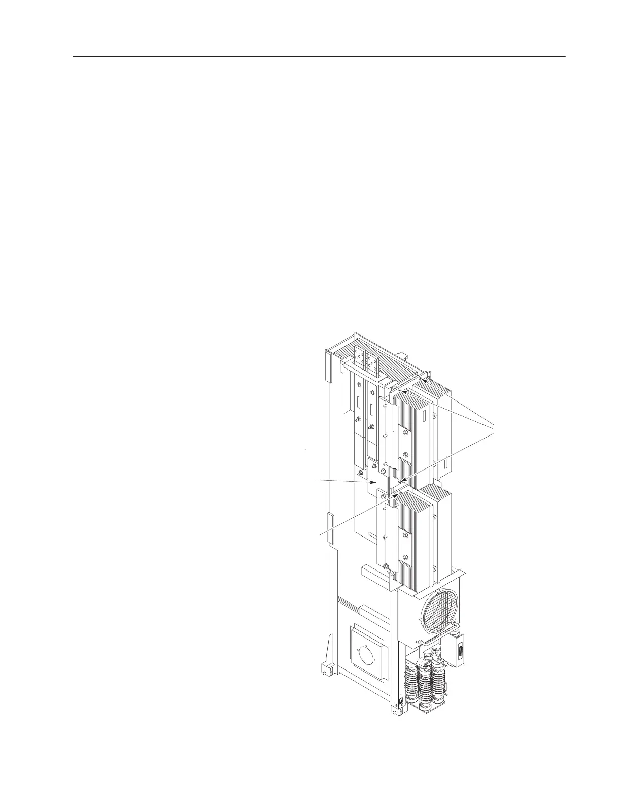
7. Remove the square shaped bus bar on the left side of the Inverter
Assembly, refer to Figure 3.18.
Figure 3.18
Left Side View
Square-Shaped
Bus Bar
Screws Attaching
SCR Back-up
Plate (2)
AB0927
Screws Attaching
Diode Back-up
Plate (4)
 Loading...


