4–15Component Test Procedures
Publication 1336 IMPACT-6.8 – November, 2002
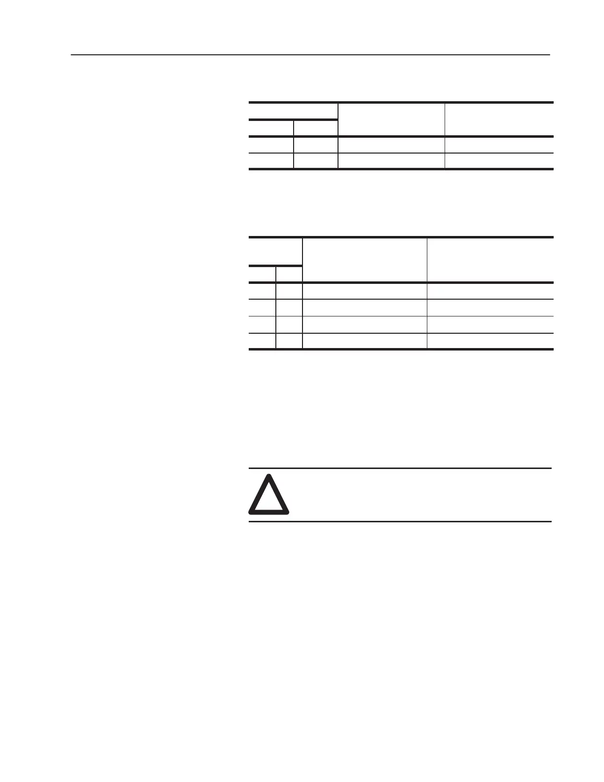
Table 4.F
Diode Readings
Meter Leads
O
R
di
g Di
d
V
+
–
1 2 1 to 3 M Ohm (not shorted) Open (not shorted)
2 1 0 to 0.4 M Ohm (not shorted) 0.3 to 0.4 V (not shorted)
5. SCR check: Connect the meter leads at the points identified in
Figure 4.7 and check for the values indicated in Table 4.G.
Table 4.G
SCR Readings
Meter
Leads
O
R
di
g Di
d
V
+
–
3 4 1 to 3 M Ohm (not shorted) Open (not shorted)
4 3 1 to 3 M Ohm (not shorted) Open (not shorted)
G 4 5 to 20 Ohm (not open) Less than 1 (not open)
4 G 5 to 20 Ohm (not open) Less than 1 (not open)
6. If SCR or Diode test fail, refer to Replacing a Diode, SCR or
Thermostat in Chapter 5, Part Replacement Procedures.
7. If SCR and Diode tests pass, re-install the following bus bars.
Refer to Table 3.A – Fastener Torque Specifications in Chapter 3,
Access Procedures.
• U-shaped bus bar
• Precharge to spine flex bus
!
ATTENTION: Replace all guards before applying
power to the drive. Failure to replace guards may result
in death or serious injury.
 Loading...


