4–14 Component Test Procedures
Publication 1336 IMPACT-6.8 – November, 2002
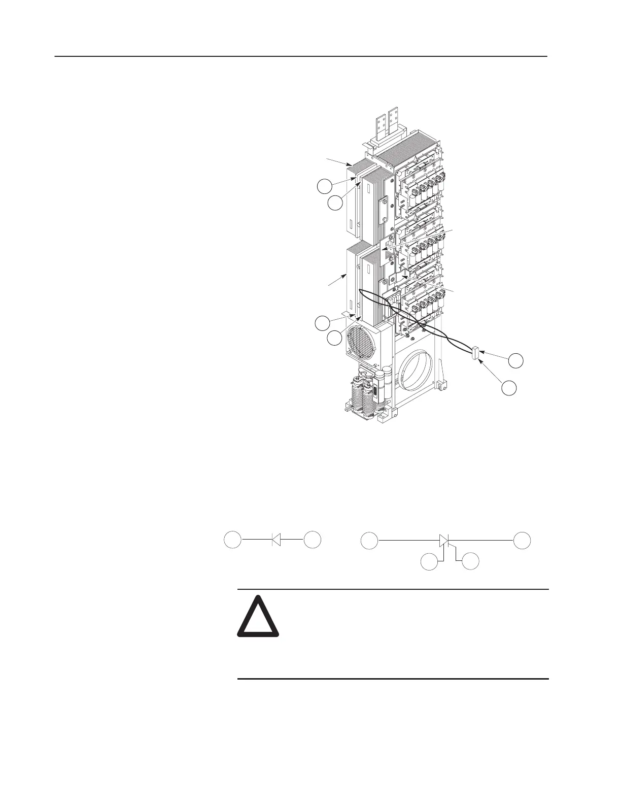
Figure 4.7
Diode and SCR Location
Diode Heat Sink
1
2
3
4
Test Location
(Diode)
Precharge to
Spine Flex Bus
U-Shaped
Bus Bar
Test Location
(SCR)
SCR Heat Sink
G
C
J1 at the Common
Bus Precharge Board
Blue
Lead
Black
Lead
Figure 4.8
Diode and SCR Circuit
12
Diode (Upper Heat Sink)
3
SCR (Lower Heat Sink)
G
C
4
Left
(Anode)
Right
(Cathode)
Left
(Cathode)
Right
(Anode)
!
ATTENTION: Resistance or voltage checks made on
the Diode or SCR heat sinks must be made to the heat
sink aluminum base plate, not the aluminum fins, refer
to Figure 4.7. The heat sinks have an epoxy bonded fin,
and many of the fins are NOT electrically connected to
the aluminum base plate.
4. Diode check: Connect the meter leads at the points identified in
Figure 4.7 and check for the values indicated in Table 4.F.
 Loading...


