5–47Part Replacement Procedures
Publication 1336 IMPACT-6.8 – November, 2002
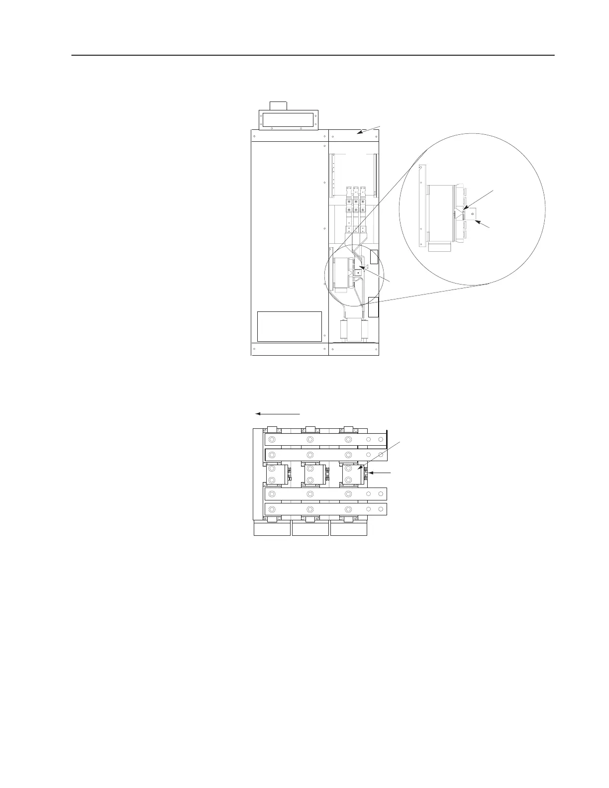
Figure 5.26
Thermal Switches
Converter Bay
Flex Bus (3)
L-Shaped
Bus Bar (3)
Thermal
Switches (3)
AB1099
Figure 5.27
Thermal Switches – Side View
Thermal Switch
L-Shaped Bus Bar
Front of Cabinet
AB1100
2. Tighten the screw on the thermal switch.
3. Bolt the L-shaped bus bar to the diode with two bolts.
4. Connect the power wires to the new thermal switch. It is not
important which power wire is attached to which end of the
thermal switch.
5. If not connected, connect the flex bus to the L-shaped bus bar.
 Loading...


