3–8 Access Procedures
Publication 1336 IMPACT-6.8 – November, 2002
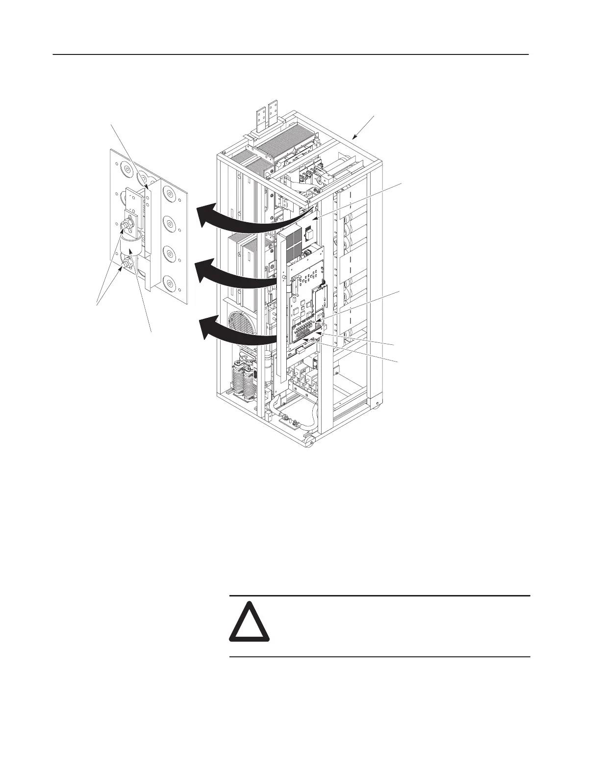
Figure 3.5
No Voltage Check
Precharge Board Mounting
Frame (Shown Unlatched
and Swung Open)
Inverter Bay w/o Cabinet
L Option Board
TB10
TB11
–DC
(Negative Capacitor Bus)
+DC
Check All Three
Bus Fuses
6. Typically, the Converter Bay door opens with quarter turn latches.
Also, if present, pull the:
• Circuit breaker handle all the way down
• Rotary disconnect handle to Off
7. Check for zero volts on incoming power lines. In particular at the
six line fuses, check both ends for zero voltage from phase to
phase and phase to ground. Refer to Figure 3.6.
!
ATTENTION: A blown fuse can create a hazard of
shock which may result in death or serious injury.
Check voltage between the reference and both ends of
all fuses.
 Loading...


