3–15Access Procedures
Publication 1336 IMPACT-6.8 – November, 2002
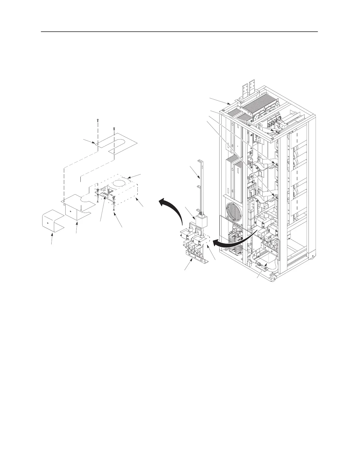
5. Remove the screws and standoffs fastening each Current
Transducer to the channels on the bay frame.
Figure 3.9
Current Transducers
AB0608A
Motor Bus
Bottom Support
Motor
Buses
Front
Cover
Clear
Insulator
Top Cover
Current
Transducer
(LEM)
Inverter
Bay
Channel
(Part of
Inverter Bay
Frame)
Harness
Connector
HV Guard
Screws
and
Standoffs
Channel
(Part of
Inverter Bay
Frame)
Motor Bus
Flex Cables
Common
Mode
Choke
Referring again to Figure 3.9 and to the following steps, remove the
Motor Buses:
1. Disconnect the Motor Buses from the Motor Bus Bottom
Support.
2. Remove Motor Bus Bottom Support.
3. Disconnect the right Motor Bus at its upper end.
4. Disconnect Motor Buses from flex cables. (This step is not
required when Motor Buses are being removed to access the
Current Transducers.)
5. Remove the Motor Buses (or tilt out the bottom to access the
Current Transducers).
 Loading...


