3–19Access Procedures
Publication 1336 IMPACT-6.8 – November, 2002
2. Remove the HV Guard that spans the bottom of the Inverter
Bay (held in place with hook-and-loop strips).
3. Remove the incoming motor connections from the Motor Cable
Terminals at the bottom right of the Inverter Bay. Refer to Figure
3.10.
Refer to Figure 3.10 and the following steps to remove the T bar
from the front of the drive:
1. Loosen the lock-down bolt between the inverter and the left arm
of the T bar.
2. Remove the T bar mounting bolt at the bottom of the T bar.
3. Remove the bolts fastening each arm of the T bar.
4. Release the Snapper Pin at the top of the T bar.
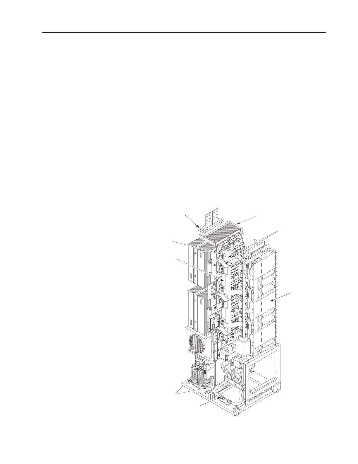
Refer to Figure 3.11 and the following steps to remove connections
and the Spine:
Figure 3.11
Disconnecting the Spine
AB0984A
Flexible Bus Bars
Spine
Nuts (18)
Inverter Bay w/o Cabinet
Capacitor Bank
Assembly
Wheel
Chocks
Inverter Assembly
Ground Cable
Inverter Assembly
 Loading...


