4–4 Component Test Procedures
Publication 1336 IMPACT-6.8 – November, 2002
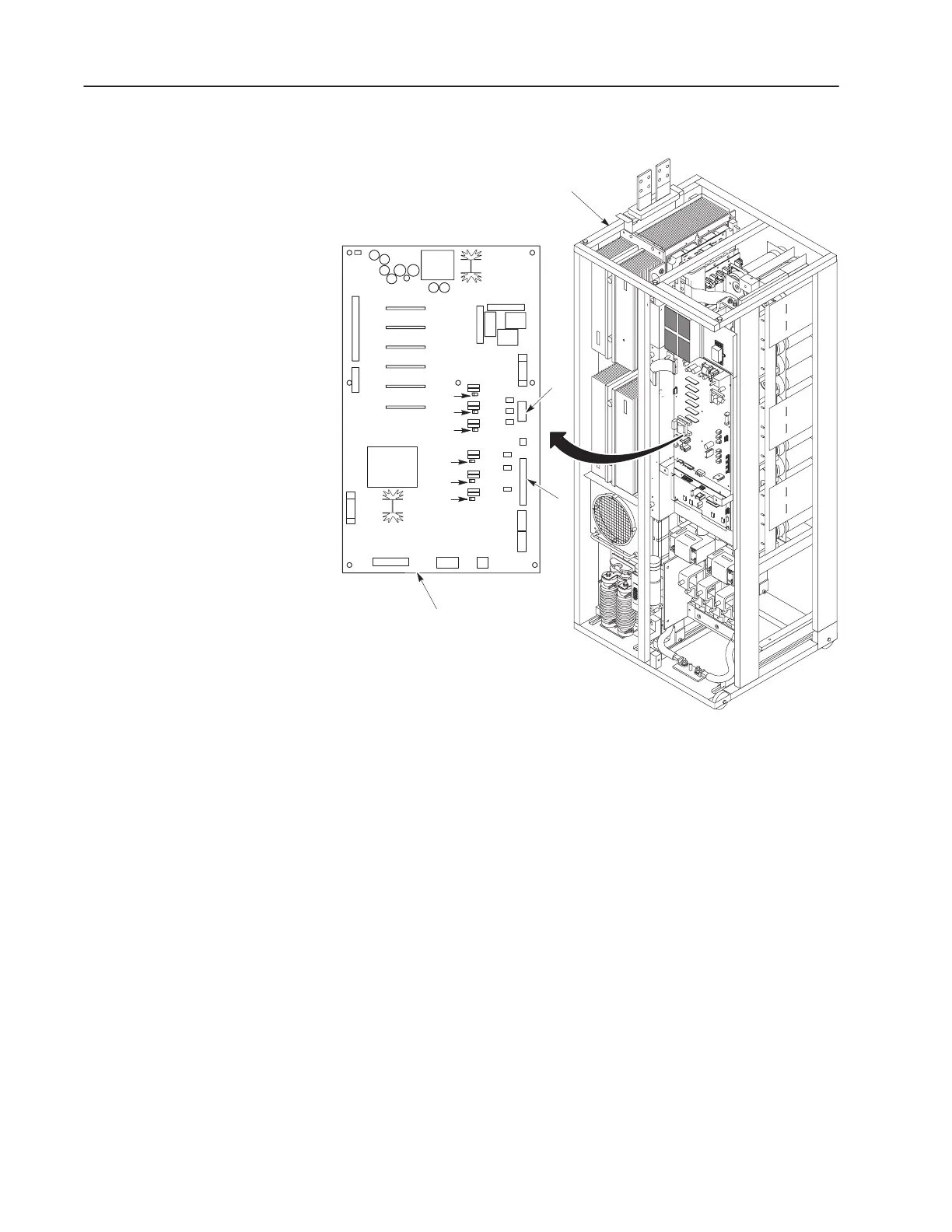
Figure 4.1
Gate Driver Board Test
Inverter Assembly w/o Cabinet
(Control Board Mounting Plate
Removed)
F3
VR2
VR3
VR5
VR6
VR1
VR4
F1
Gate Driver Board
(Located Behind the
Control Board)
D78
D71
D72
D65
D66
D10
J7
J8
6. Check all six reverse-bias Zener diodes: D10, D66, D65, D72,
D71, and D78. Table 4.B shows meter connections at the
components and ideal meter readings for those connections. Refer
to Figure 4.1 for component locations.
7. Replace the Gate Driver Board if your readings do not match the
table, or if any diode is shorted or open in both directions. Refer to
Replacing the Gate Driver Board in Chapter 5, Part Replacement
Procedures.
 Loading...


