Rockwell Automation Publication 750-TG100B-EN-P - June 2019 105
Frame 7 Components Chapter 6
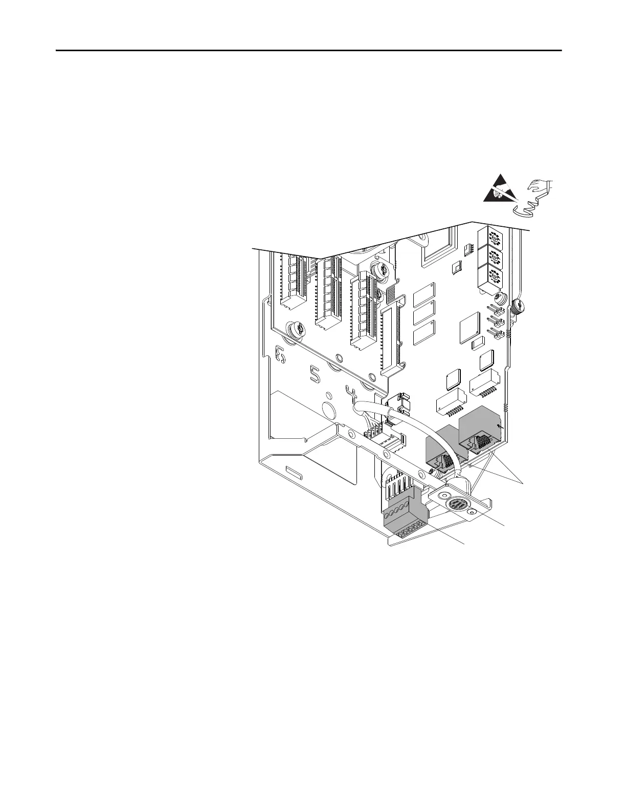
10. Disconnect any Ethernet cables from the ports on the bottom of the main
control board.
11. Disconnect the plug-in terminal block (TB1) on the bottom of the main
control board.
12. Disconnect the HIM plug-in terminal block for the mini-DIN (port 2)
connector on the control board.
13. If an option module is installed, complete these steps:
a. Disconnect the plug-in terminal blocks.
b. Loosen the two captive thumb screws that secure the option module to
the control pod chassis and remove the option module. Final torque for
re-assembly is 0.45 N•m (4 lb•in).
Control Pod Shown Removed from Drive and
Outer Control Pod Chassis for Clarity Only.

 Loading...


