EasyManuals Logo

Rockwell Automation Allen-Bradley PowerFlex 750 Series Service Manual

Rockwell Automation Allen-Bradley PowerFlex 750 Series
352 pages
To Next Page IconTo Next Page
To Previous Page IconTo Previous Page
Page #272 background imageLoading...
Page #272 background image
272 Rockwell Automation Publication 750-TG100B-EN-P - June 2019
Chapter 9 Power Bay Components
8. If the top-most receptacle on the back of the LCL filter module contains a
DC capacitor, remove the capacitor. See Remove the LCL Filter Capacitor
Assembly on page 264
. If the top-most receptacle on the back of the LCL
filter module does not contain a DC capacitor, complete steps a and b.
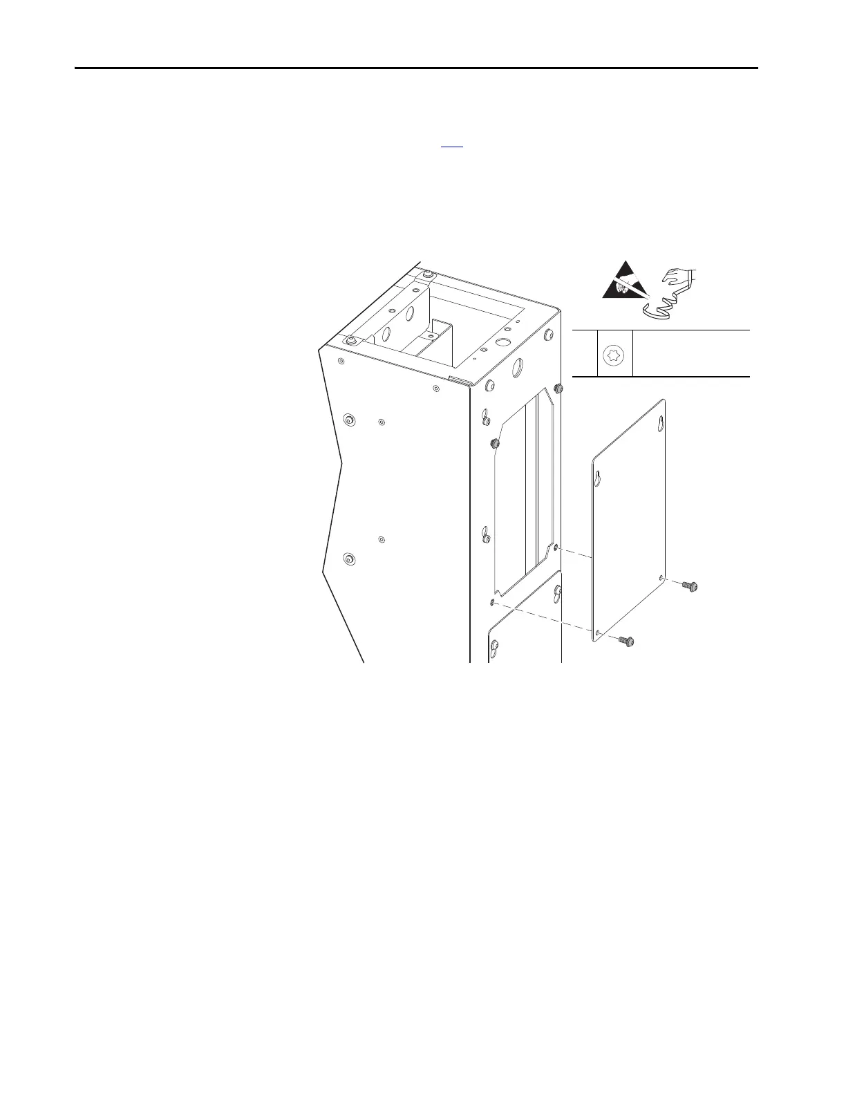
a. Remove the lower two M6 x 16 mm torx screws that secure the cover to
the chassis.
b. Loosen the upper two M6 x 16 mm torx screws that secure the cover to
the chassis and remove the cover.
8
M6 x 16 mm
T30
12.5 N•m (110.6 lb•in)
=

Table of Contents

Other manuals for Rockwell Automation Allen-Bradley PowerFlex 750 Series

Questions and Answers:

Question and Answer IconNeed help?

Do you have a question about the Rockwell Automation Allen-Bradley PowerFlex 750 Series and is the answer not in the manual?

Rockwell Automation Allen-Bradley PowerFlex 750 Series Specifications

General IconGeneral
BrandRockwell Automation
ModelAllen-Bradley PowerFlex 750 Series
CategoryDC Drives
LanguageEnglish

Related product manuals