Rockwell Automation Publication 750-TG100B-EN-P - June 2019 273
Power Bay Components Chapter 9
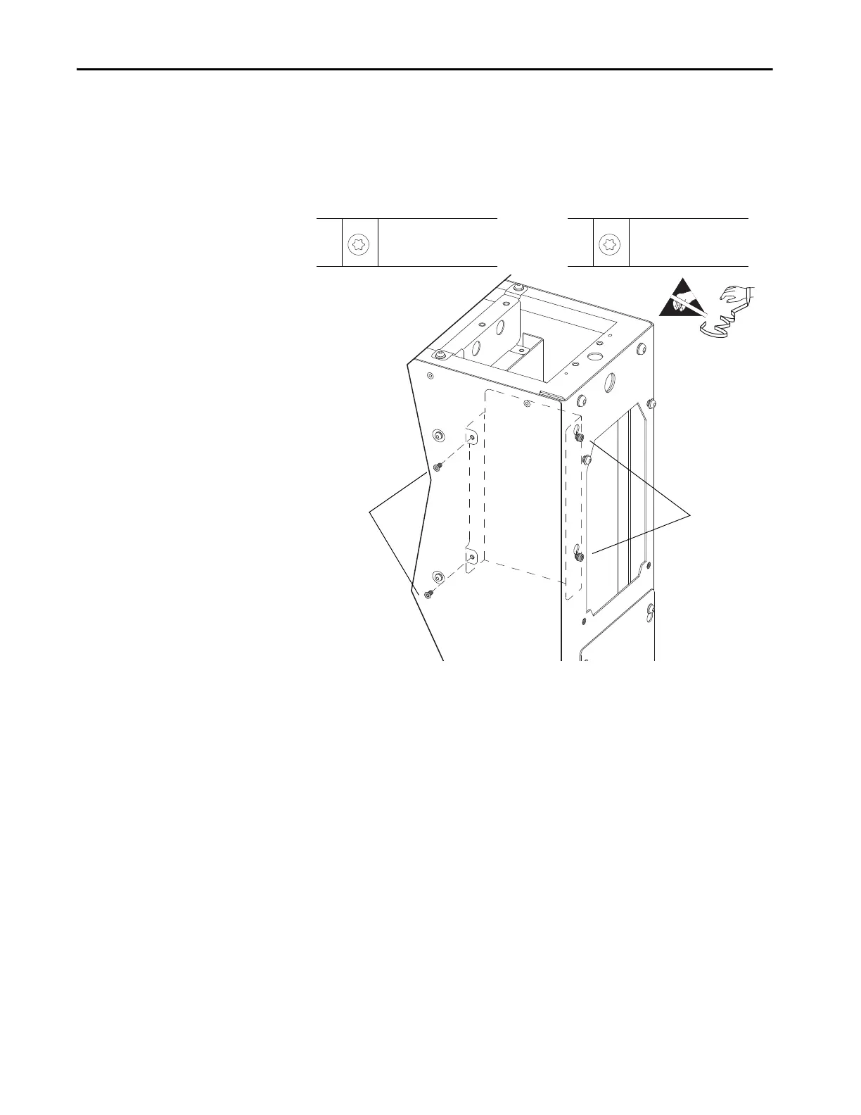
9. Remove the two M5 x 10 mm torx screws that secure the current sense
circuit board tray to the side of the chassis.
10. While supporting the circuit board tray, loosen, but do not remove, the
two M5 x 12 mm torx screws that secure the current sense circuit board
tray to the back of the chassis and lift the tray off the screws.
11. Cut the cable ties that secure the wires to the circuit board tray.
12. Disconnect these connectors from the current sense circuit board:
•P8 from J8
•P5 from J5
•P6 from J6
• P13 from J13
•P4 from J4
•P1 from J1
• P14 from J14 (must be reused to maintain the rating of the module)
13. Remove the circuit board tray from the module chassis.
9
M5 x 10 mm
T25
4 N•m (35.4 lb•in)
10
M5 x 12 mm
T25
4 N•m (35.4 lb•in)

 Loading...


