Rockwell Automation Publication 750-TG100B-EN-P - June 2019 297
Start Up After Repairs Chapter 11
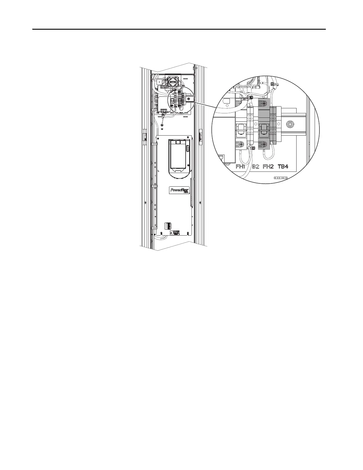
• For control bays, measure terminal L at FH2-2 and terminal N at
terminal block TB4.
4. For all products, perform phase to ground resistance tests to verify that
there are no shorts on the following locations:
In a frame 7 enclosure and frame 8…15 input bay:
• Use the circuit breaker output (CB1 SEC) testpoints R/L1, S/L2, and
T/L3 to measure L to chassis GND.
• Use the fused disconnect output (FD1 SEC) testpoints R, S, and T to
measure L to chassis GND.
• Use the DC bus testpoints +DC and –DC to measure +DC to chassis
GND, and –DC to chassis GND.
In a frame 7 enclosure and frame 8…15 power bay:
• Use the DC bus testpoints +DC and –DC on the front of the power
modules to measure +DC to chassis GND, and –DC to chassis GND.
5. If the measured value of any resistance test is less than 1 k, troubleshoot
to find the short, correct the problem, and repeat step 4.
6. For any module or component that has been removed and re-installed,
complete the following:
• Verify that all hardware connections have been replaced and are
properly torqued.

 Loading...


