EasyManuals Logo

Rockwell Automation Allen-Bradley PowerFlex 750 Series Service Manual

Rockwell Automation Allen-Bradley PowerFlex 750 Series
352 pages
To Next Page IconTo Next Page
To Previous Page IconTo Previous Page
Page #78 background imageLoading...
Page #78 background image
78 Rockwell Automation Publication 750-TG100B-EN-P - June 2019
Chapter 5 Frame 6 Components
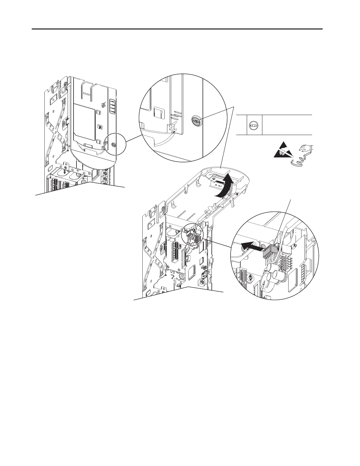
4. Loosen the screw that secures the HIM bezel to the pod chassis, and rotate
the bezel up to a 90° horizontal position.
5. Disconnect the HIM cable from the port on the main control board.
4
5
=
4
M3 x 6.4 mm
T15 or F - 5 mm (0.19 in.)
0.45 N•m (4 lb•in)
Control Pod Shown Removed
from Drive for Clarity Only.

Table of Contents

Other manuals for Rockwell Automation Allen-Bradley PowerFlex 750 Series

Questions and Answers:

Question and Answer IconNeed help?

Do you have a question about the Rockwell Automation Allen-Bradley PowerFlex 750 Series and is the answer not in the manual?

Rockwell Automation Allen-Bradley PowerFlex 750 Series Specifications

General IconGeneral
BrandRockwell Automation
ModelAllen-Bradley PowerFlex 750 Series
CategoryDC Drives
LanguageEnglish

Related product manuals