Design Guidelines
Transport System Configuration
QuickStick HT User Manual 119
Rockwell Automation Publication MMI-UM007F-EN-P - September 2020
Transport System Configuration
All examples that are provided are for horizontal track layouts unless otherwise specified. The
guideway is shown in cross-section in Figure 3-37.
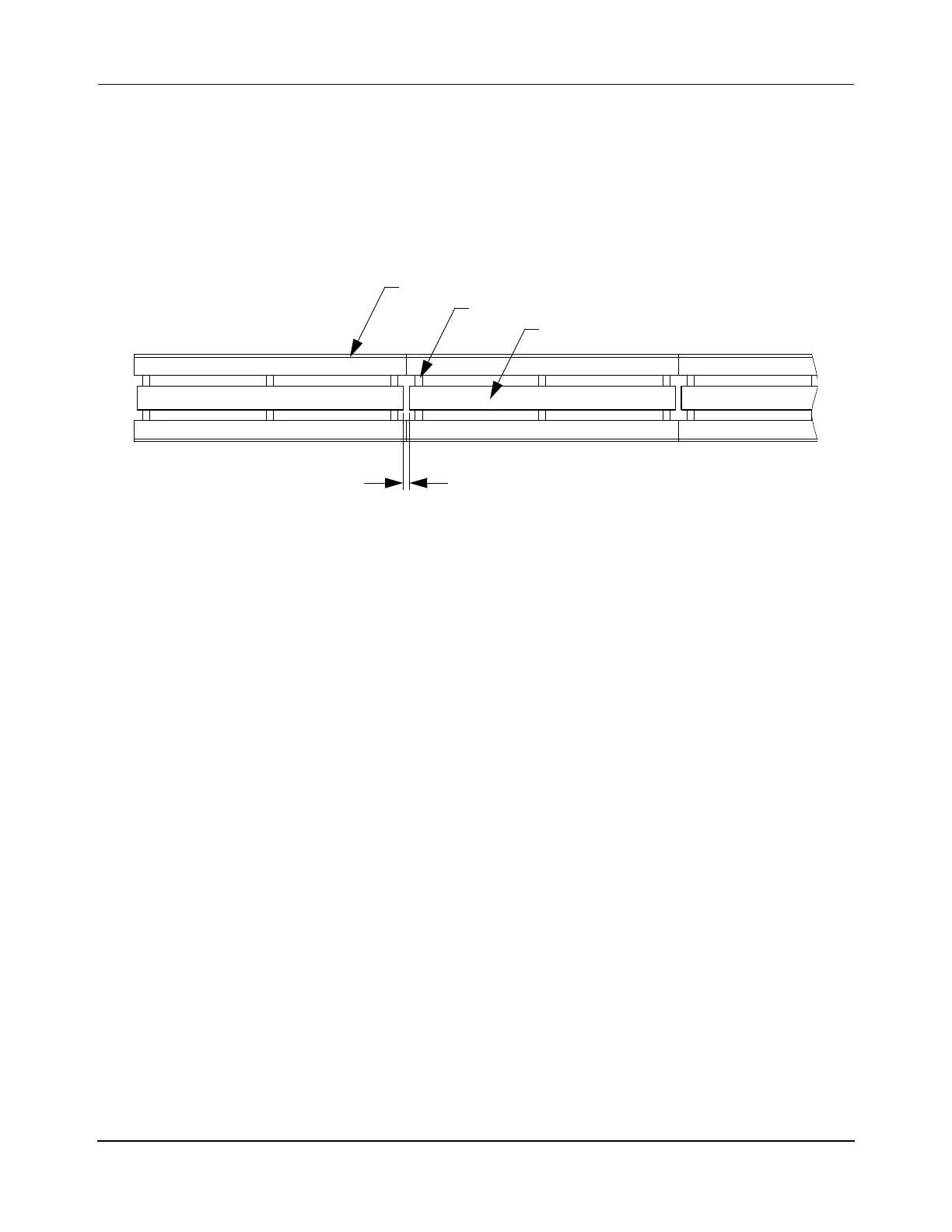
Straight Track Configuration
Figure 3-43: Straight Track Configuration
• Node types at the beginning of a path: Simple, Relay, Terminus, Gateway.
• Node types at the end of a path: Relay, Terminus, Gateway.
• Keep the Motor Gaps consistent over the length of the path and over the entire system
if possible to make creation of the Node Controller Configuration File simpler.
NOTE: Different size gaps between motors must be identified in the Node Controller
Configuration File (see the QuickStick Configurator User Manual,
MMI-UM009).
Guideway
Motor Mount
QSHT Motor
Top View
Motor Gap
 Loading...

