Installation
Transport System Installation
192 MagneMotion
Rockwell Automation Publication MMI-UM007F-EN-P - September 2020
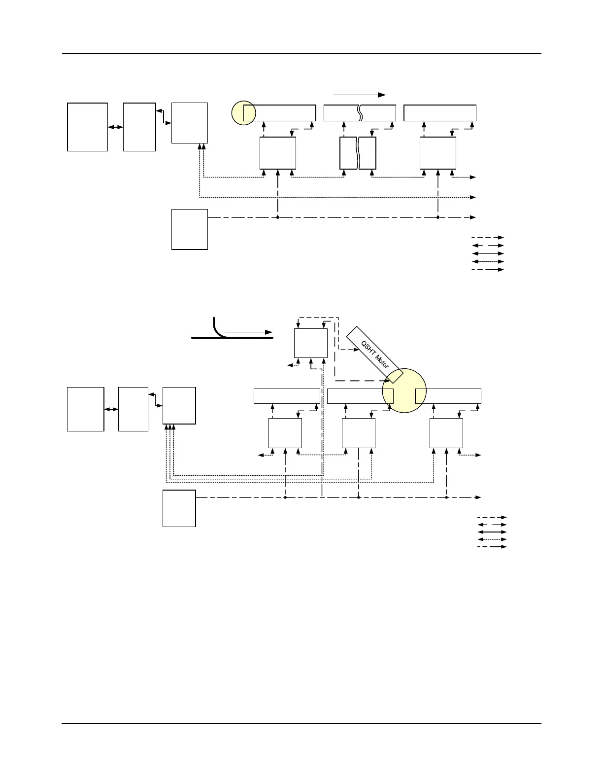
RS-422 Motor Communications
Figure 5-5: Simplified Representation of RS-422 Motor Connections
Figure 5-6: Simplified Representation of RS-422 Motor Connections in a Merge Switch
Installing Motor and RS-422 Motor Controller Communication Cables
See Figure 4-9 for the connection locations on the QSHT motors and Figure 4-16 and
Figure 4-17 for the connection locations on the QSMC motor controllers. See the Node Con-
troller Hardware User Manual, MMI-UM013, for the communication connection locations
on the node controllers. See Figure 5-5 and Figure 5-6 for simplified diagrams of the wiring
and Figure 5-7 for a detailed example.
When connecting the motor controllers to the node controllers, both ends of a path do not need
to connect to the same node controller. However, all connections to the motor controllers for
Simple QSHT Motor
Host
Controller
QSHT Motor
Enet
Switch
HLC &
Node
Controller
Power
Supply
Power
To Next Motor
Controller in Path
Upstream Downstream
To Next Motor
Controller in Path
From Last Motor
Controller in Path
RS-422
Downstream
Motor
Controller
Motor
Controller
RS-422
Power
Drive
Sense
Ethernet
Merge
Enet
Switch
HLC &
Node
Controller
RS-422
Upstream Downstream
From Previous Motor
Controller in Path
Upstream
Switch Configuration
Downstream
To Next Motor
Controller in Path
QSHT Motor QSHT Motor QSHT Motor
Motor
Controller
Motor
Controller
Motor
Controller
Motor
Controller
Power
Supply
Power
To Next Motor
Controller in Path
From Previous Motor
Controller in Path
RS-422
Power
Drive
Sense
Ethernet
Host
Controller
 Loading...

