QSHT 5700 Inverter Safe Torque-off Function
Hardwired Safe Torque-off
274 MagneMotion
Rockwell Automation Publication MMI-UM007F-EN-P - September 2020
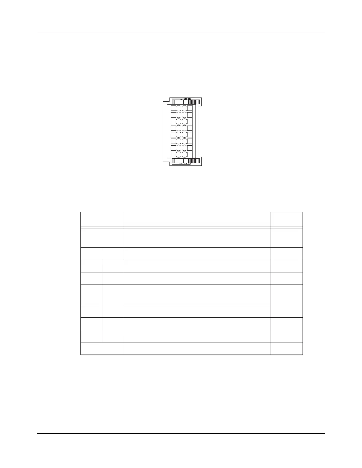
Safe Torque-off Connector Data
Two rows of eight pins are provided for making inverter-to-inverter connections. The inverter
has pins designated for inverter A and inverter B.
Figure 7-5: Pin Orientation for 16-pin Safe Torque-off (STO) Connector
Table 7-4: Safe Torque-off Connector Pinouts
STO Pin Description Signal
1 Safety bypass plus signal. Connect to both safety
inputs to disable safe torque-off function.
SB+
2 10 Safe stop input channel 1, inverter A. S1A
3 11 Safe stop input common, inverter A. SCA
4 12 Safe stop input channel 2, inverter A. S2A
5 13 Safety bypass minus signal. Connect to safety com-
mon to disable safe torque-off function.
SB-
6 14 Safe stop input channel 1, inverter B. S1B
7 15 Safe stop input common, inverter B. SCB
8 16 Safe stop input channel 2, inverter B. S2B
9N/C —
S1A
SCA
S2A
SB-
S1B
SCB
1
2
3
4
5
6
7
8
9
10
11
12
13
14
15
16
SB+/NC
S2B
MMI-HT-C2198-D032
Safety (STO) Connector Plug
 Loading...

