Specifications and Site Requirements
Electrical Specifications
158 MagneMotion
Rockwell Automation Publication MMI-UM007F-EN-P - September 2020
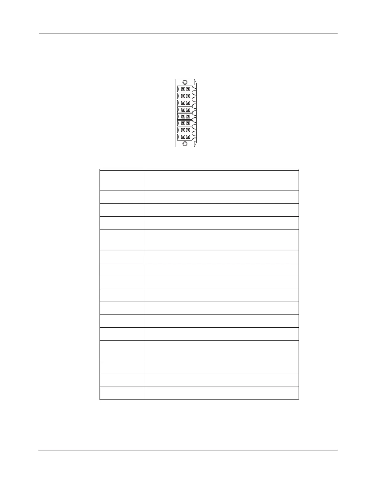
Table 4-38: QSHT 5700 Inverter Safety Connector Pinout
1 SB+ this is used to enable motion when safety is not
required by jumpering to the SS_IN pins
2 SS_IN_CH0 (Safe-stop input channel 1) – Inverter A
3 SS_COM (Safe-stop input common)
4 SS_IN_CH1 (Safe-stop input channel 2) – Inverter A
5 SB- this is used to enable motion when safety is not
required by jumpering to the SS_COM pins
6 SS_IN_CH0 (Safe-stop input channel 1) – Inverter B
7 SS_COM (Safe-stop input common)
8 SS_IN_CH1 (Safe-stop input channel 2) – Inverter B
9 Not Connected
10 SS_IN_CH0 (Safe-stop input channel 1) – Inverter A
11 SS_COM (Safe-stop input common)
12 SS_IN_CH1 (Safe-stop input channel 2) – Inverter A
13 SB- this is used to enable motion when safety is not
required by jumpering to the SS_COM pins
14 SS_IN_CH0 (Safe-stop input channel 1) – Inverter B
15 SS_COM (Safe-stop input common)
16 SS_IN_CH1 (Safe-stop input channel 2) – Inverter B
SB+/NC
S1A
SCA
S2A
SB-
S1B
SCB
S2B
1 9
8 16
 Loading...

