Design Guidelines
Transport System Design
QuickStick HT User Manual 83
Rockwell Automation Publication MMI-UM007F-EN-P - September 2020
Loop Paths
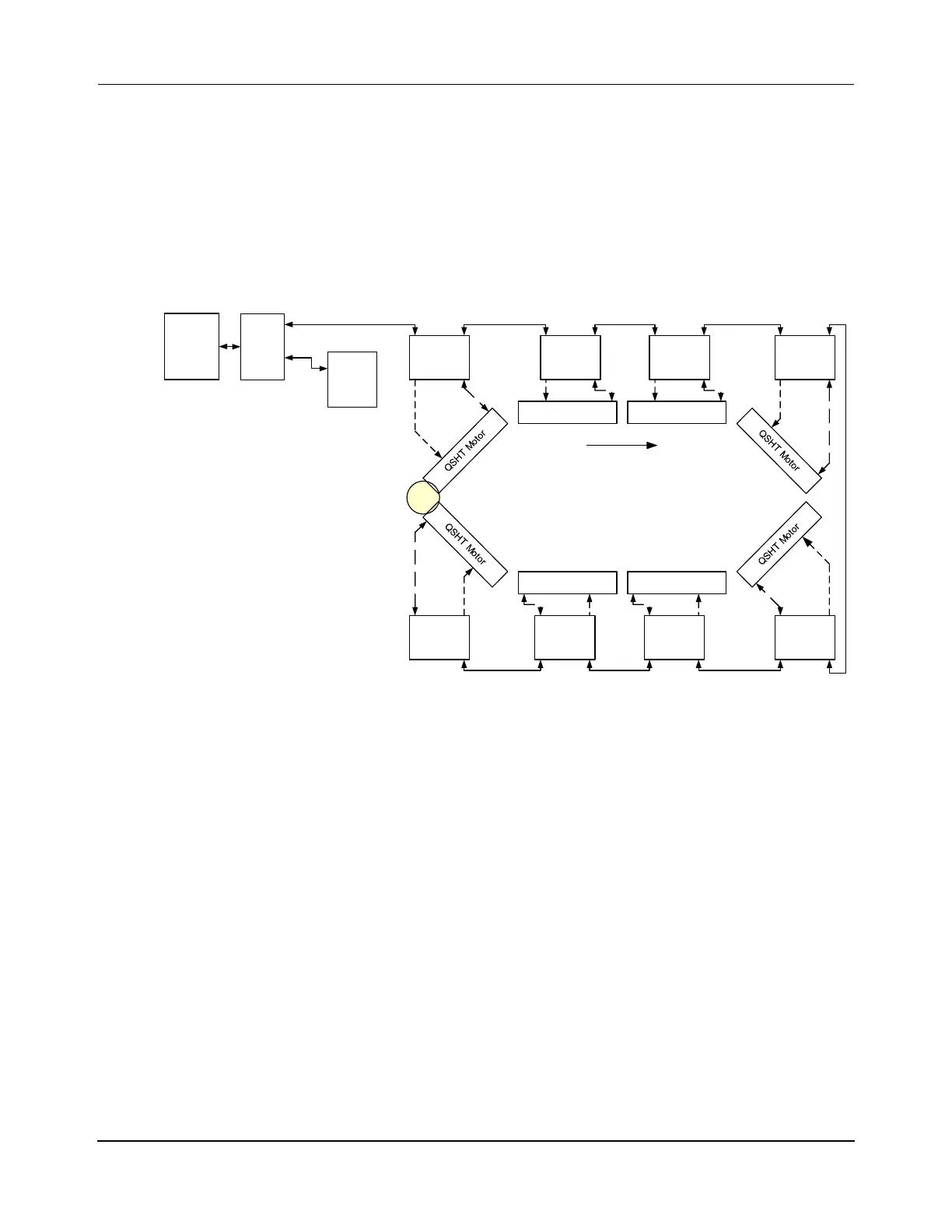
The following figures show simplified connection diagrams of the different methods for con-
necting a loop of motors using Ethernet. The specific connection method that is used depends
on the application for the motors.
Figure 3-20: Ethernet Motor Wiring – One Path, One Ethernet Chain
Relay
Host
Controller
Loop Transport System (Recommended):
One Ethernet Connection to Switch
Power Supply - Inline or Star
One Chain
One Path
P1M1
x.y.1.1
P1M4
x.y.1.4
P1M5
x.y.1.5
P1M8
x.y.1.8
P1M2
x.y.1.2
QSHT Motor
QSHT Motor
QSHT 5700
Inverter
P1M7
x.y.1.7
P1M3
x.y.1.3
QSHT Motor
QSHT 5700
Inverter
P1M6
x.y.1.6
QSHT 5700
Inverter
QSHT 5700
Inverter
QSHT 5700
Inverter
QSHT 5700
Inverter
QSHT Motor
QSHT 5700
Inverter
QSHT 5700
Inverter
Enet
Switch
Ethernet
x.y.0.10
HLC &
Node
Controller
Downstream
 Loading...

