Installation
Check-out and Power-up
QuickStick HT User Manual 223
Rockwell Automation Publication MMI-UM007F-EN-P - September 2020
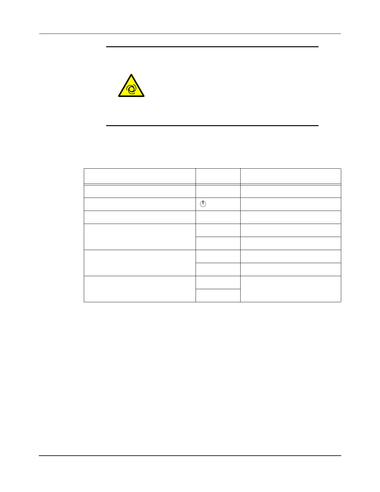
The indicators on the components of the QuickStick HT transport system are lit as
shown in Table 5-7.
6. If power-up was successful, the QuickStick HT transport system is ready to accept
commands. If however, the power-up sequence was unsuccessful, see Troubleshooting
on page 286.
7. Create the Node Controller Configuration File for the transport system (see Software
Configuration on page 219 and the QuickStick Configurator User Manual,
MMI-UM009).
8. Set the IP address for each node controller. See the Node Controller Interface User
Manual, MMI-UM001, for more details. If EtherNet/IP is being used, see the Quick-
Stick Configurator User Manual, MMI-UM009, for additional configuration informa-
tion.
9. Configure one node controller as the HLC. See the Node Controller Interface User
Manual, MMI-UM001, for more details.
AUTOMATIC MOTION HAZARD: The host con-
troller initiates all motion control to the QuickStick
HT transport system. It is the responsibility of the
user to initiate a safe startup of all QSHT compo-
nents.
Do not attempt to operate the QSHT transport system
until all setup procedures that are described in this
chapter have been completed.
Table 5-7: Startup Indicators
Component Indicator Status
Node Controller, NC-S Power On (green)
Node Controller, NC-E (Power) On (blue)
Node Controller, NC-12 Power On (green)
Motor Controller, QSMC Power On (red)
Status On (green)
Inverter, QSHT 5700 NET See Table 4-44
MOD See Table 4-45
Power Supply,
2198-Pxxx DC-bus NET
See Kinetix 5700 Servo Drives
User Manual, 2198-UM002
MOD
 Loading...

