Installation
Transport System Installation
202 MagneMotion
Rockwell Automation Publication MMI-UM007F-EN-P - September 2020
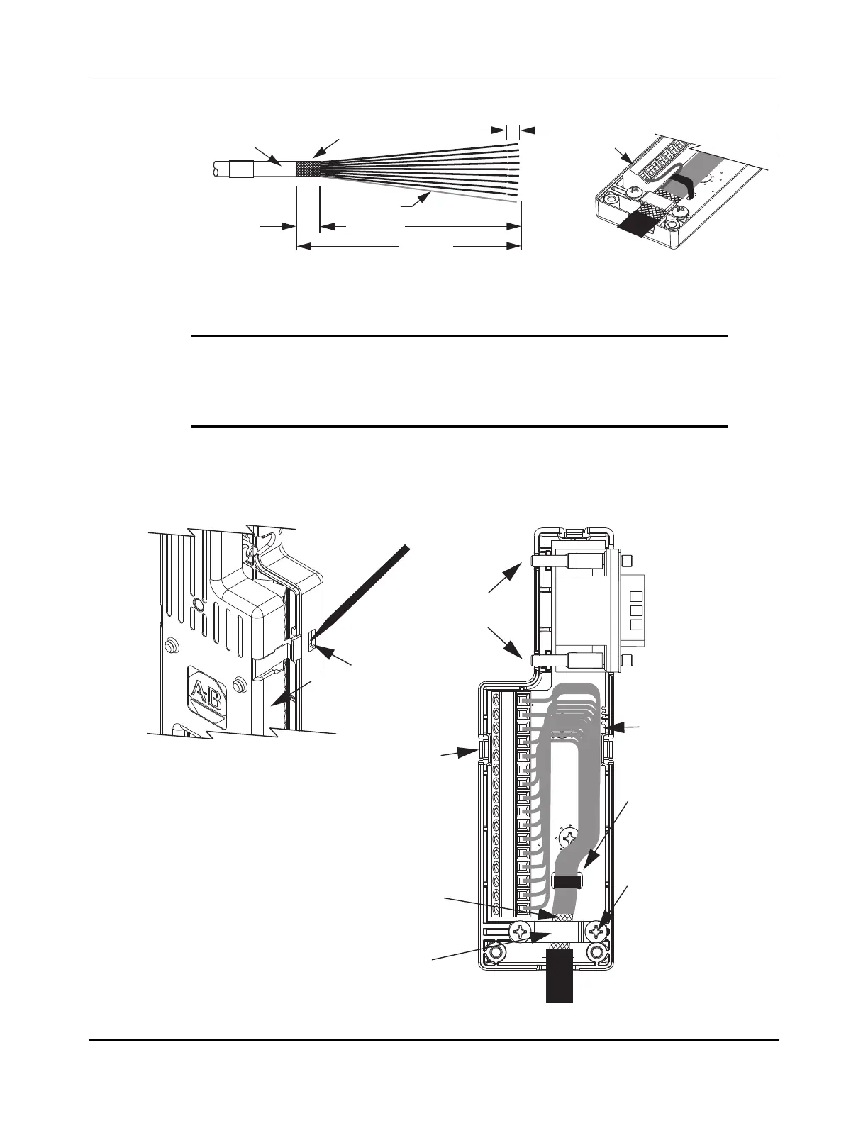
Figure 5-12: Feedback Cable
Install the Connector Kit
To install the connector kit, see Figure 5-13, Figure 5-14, and Table 5-5.
Figure 5-13: Wiring the Connector Kit
IMPORTANT The drain wire from the 2090-Series motor cable must be
connected to pin 16. If the cable does not include a drain
wire, create one from the overall shield during wire prepara-
tion and connect it to pin 16.
16 15 14 13 12 11 10
12.0 (0.5)
Cable Shield
Drain Wire
Cable Jacket
5.0 (0.2)
110 (4.3)
97 (3.8)
Drain Wire
All Dimensions in Millimeters [Inches]
Pull
Depress
Snap-fit
Mounting
Screws
Snap-fits
(3x)
Clamp Screws
Exposed Shield Aligned
(2X)
15-pin D-sub to
Universal (UFB)
Connector
Service Loops
Tie Wrap
(Recommended for
Stress Relief and
Wire Management)
Under the Shield Clamp
Shield Clamp
 Loading...

