Design Guidelines
Transport System Configuration
120 MagneMotion
Rockwell Automation Publication MMI-UM007F-EN-P - September 2020
Curve Track Configuration
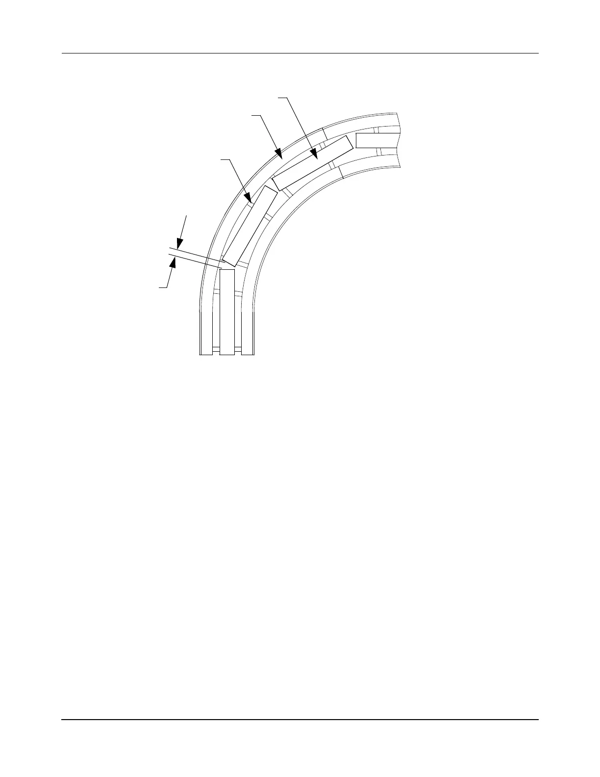
Figure 3-44: Curve Track Configuration
• Node types at the beginning of a path: Simple, Relay, Terminus, Gateway.
• Node types at the end of a path: Relay, Terminus, Gateway.
• Minimum radius is determined by motor length, and magnet array/vehicle length.
• May require a vehicle with dual magnet arrays (see Figure 3-32, Magnet Array to
Motor Alignment, on page 107).
• Motors may need to be configured as being On Curve in the Node Controller Config-
uration File.
• Keep the Motor Gaps consistent over the length of the curve in the guideway.
NOTE: Different size gaps between motors must be identified in the Node Controller
Configuration File (see the QuickStick Configurator User Manual,
MMI-UM009).
Guideway
Motor Mount
QSHT Motor
Motor Gap
Top View
 Loading...

