Installation
Transport System Installation
QuickStick HT User Manual 205
Rockwell Automation Publication MMI-UM007F-EN-P - September 2020
Installing QSMC Motor Controller Power Cables
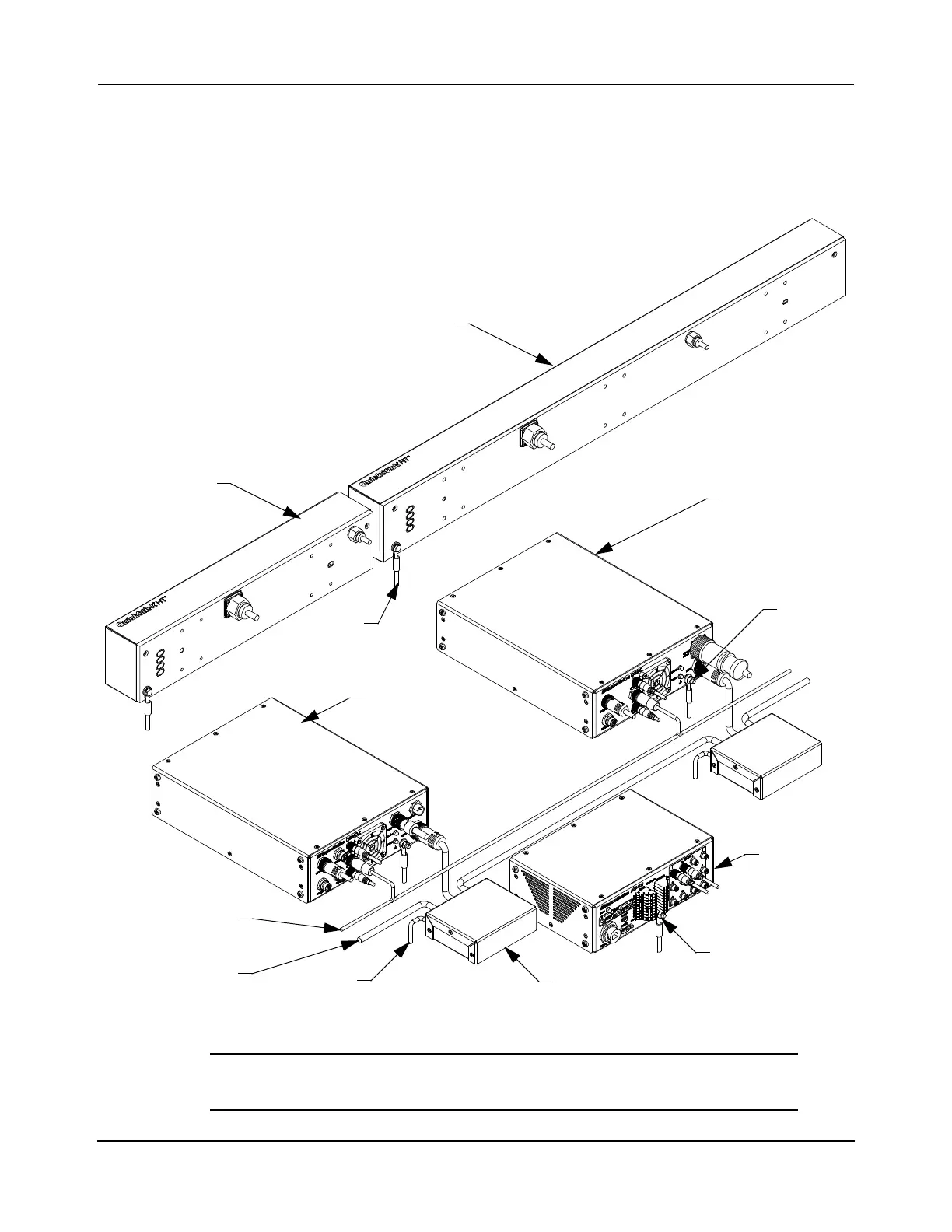
See Figure 4-16 and Figure 4-17 for the power connection locations on the QSMC motor con-
trollers in the QSHT transport system. See Figure 5-5 and Figure 5-6 for simplified diagrams
of the wiring. Figure 5-15 shows the power connections being made to the motor controllers.
Figure 5-15: QSHT Power Connections
NOTICE If a user-supplied power supply is used, it must be
NRTL/ATL approved.
Node
1/2 m QSHT
QSMC
Motor Controller
D
o
w
n
s
t
r
e
a
m
U
p
s
t
r
e
a
m
1m QSHT
24V DC Cable
Controller
HVDC Cable
(typical)
Power Junction Box
QSMC-2
Motor Controller
Ground
Ground
Ground
Ground
(typical)
(typical)
 Loading...

