Specifications and Site Requirements
Electrical Specifications
QuickStick HT User Manual 133
Rockwell Automation Publication MMI-UM007F-EN-P - September 2020
Electrical Specifications
Motors (Stators)
• 1 m – See QSMC Motor Controller on page 127 for the electrical specifications. See 1
Meter Motor on page 124 for the mechanical drawing.
•1/2m – See QSMC-2 Motor Controller on page 128 for the electrical specifications.
See 1/2 Meter Motor on page 125 for the mechanical drawing.
• 1/2 m Double-wide – See QSMC Motor Controller on page 127 for the electrical spec-
ifications. See 1/2 Meter Double-wide Motor on page 126 for the mechanical drawing.
NOTE: The motor power is supplied by the external QSMC motor controller or QSHT 5700
inverter, see QSMC Motor Controller on page 142 or QuickStick HT 5700 Inverter
on page 154 as appropriate for power requirements. All power wiring between the
motor drive and the motor must be capable of carrying the full load.
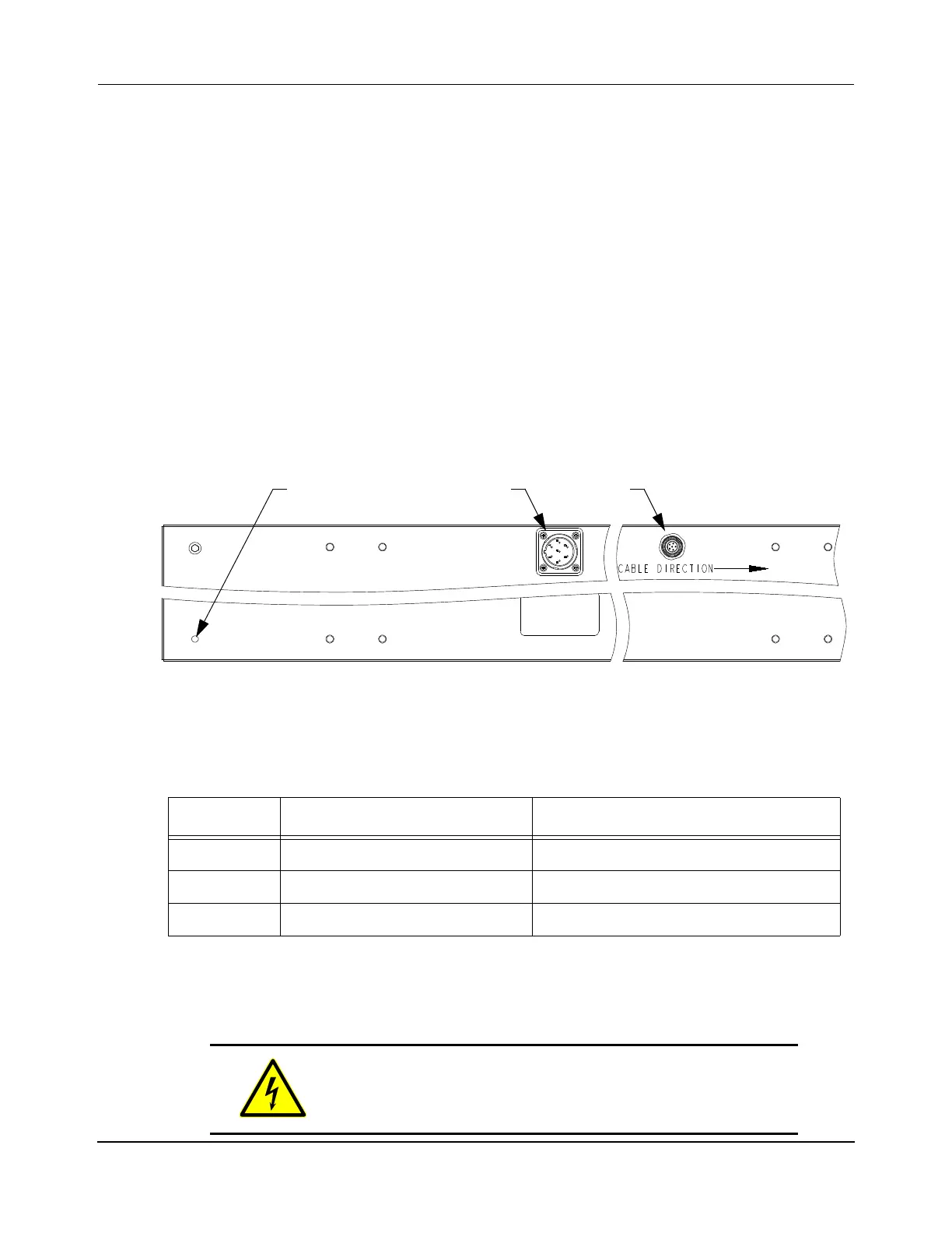
Figure 4-9: Motor Electrical Connections
NOTE: The drive and sense cables have a 90° bend at the motor connector. The bend is
located such that the cable direction is as shown in Figure 4-9 when connected.
Table 4-2: Motor Connections
Label Description Connector Type
Drive Motor block phase power 3-Point Bayonet, Size 16S, 7-Pin, Male
Sense Motor block control signals M12 Eurofast, 6-Pin, Male
Ground Motor chassis ground M6 x 1–6H, 8.0 mm max depth
SHOCK HAZARD: 400V DC maximum, 15 A maximum.
DC power must be disconnected before servicing.
Bottom View
SenseDrive
Upstream Downstream
Ground
 Loading...

