Design Guidelines
Transport System Configuration
QuickStick HT User Manual 121
Rockwell Automation Publication MMI-UM007F-EN-P - September 2020
Switch Configuration
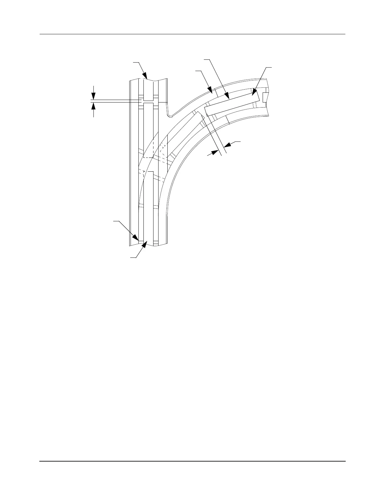
Figure 3-45: Switch Configuration
• Node types at switch: Merge, Diverge.
• Provides a merge of two paths into one (straight entry, curve entry, merged exit).
• Provides a diverge from one path into two (single entry, curve exit, straight exit).
• Requires a switching mechanism (electromagnetic or mechanical).
• Minimum radius is determined by motor length, and magnet array/vehicle length.
• May require a vehicle with dual magnet arrays (see Figure 3-32, Magnet Array to
Motor Alignment, on page 107).
• Motors in the curve section may need to be configured as being On Curve in the Node
Controller Configuration File.
• Motor Gaps can vary from section to section of the guideway (entry, exit, curve), but
keep the motor gaps consistent in each section of the guideway.
NOTE: Different size gaps between motors must be identified in the Node Controller
Configuration File (see the QuickStick Configurator User Manual,
MMI-UM009).
Guideway
Straight Entry/Straight Exit
QSHT Motor
Straight Motor Gap
Curve Entry/Curve Exit
Merged Exit/Single Entry
Motor Mount
Curve Motor Gap
Top View
 Loading...

