Installation
Transport System Installation
208 MagneMotion
Rockwell Automation Publication MMI-UM007F-EN-P - September 2020
Installing QSHT 5700 Inverter Power Cables
See Figure 4-20 for the power connection locations on the QSHT 5700 inverters. See the
Kinetix 5700 Servo Drives User Manual, 2198-UM002, for the power connector locations on
the 2198-Pxxx DC-bus power supplies in the QuickStick HT transport system. See Figure 5-8
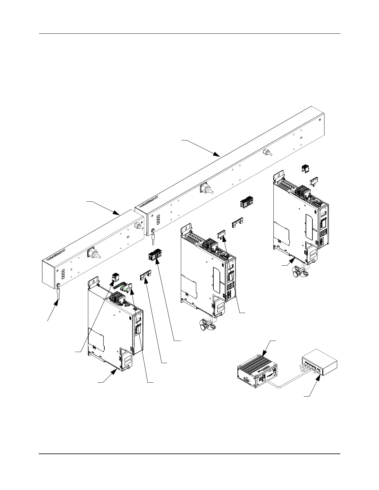
and Figure 5-9 for simplified diagrams of the wiring. Figure 5-16 shows the shared bus power
connections being made to the inverters.
Figure 5-16: QSHT Power Connections
Node
1/2 m QSHT
D
o
w
n
s
t
r
e
a
m
U
p
s
t
r
e
a
m
1m QSHT
24V DC Bus Bars
Controller
Ground
QSHT 5700
Inverter
2198-Pxxx
DC Bus
Power Supply
Ethernet Switch
24V DC T-Connectors
24V DC Input Connector
DC-bus Link, 55 mm
DC-bus
End Cap
(2X)
(typical)
(typical)
(typical)
 Loading...

