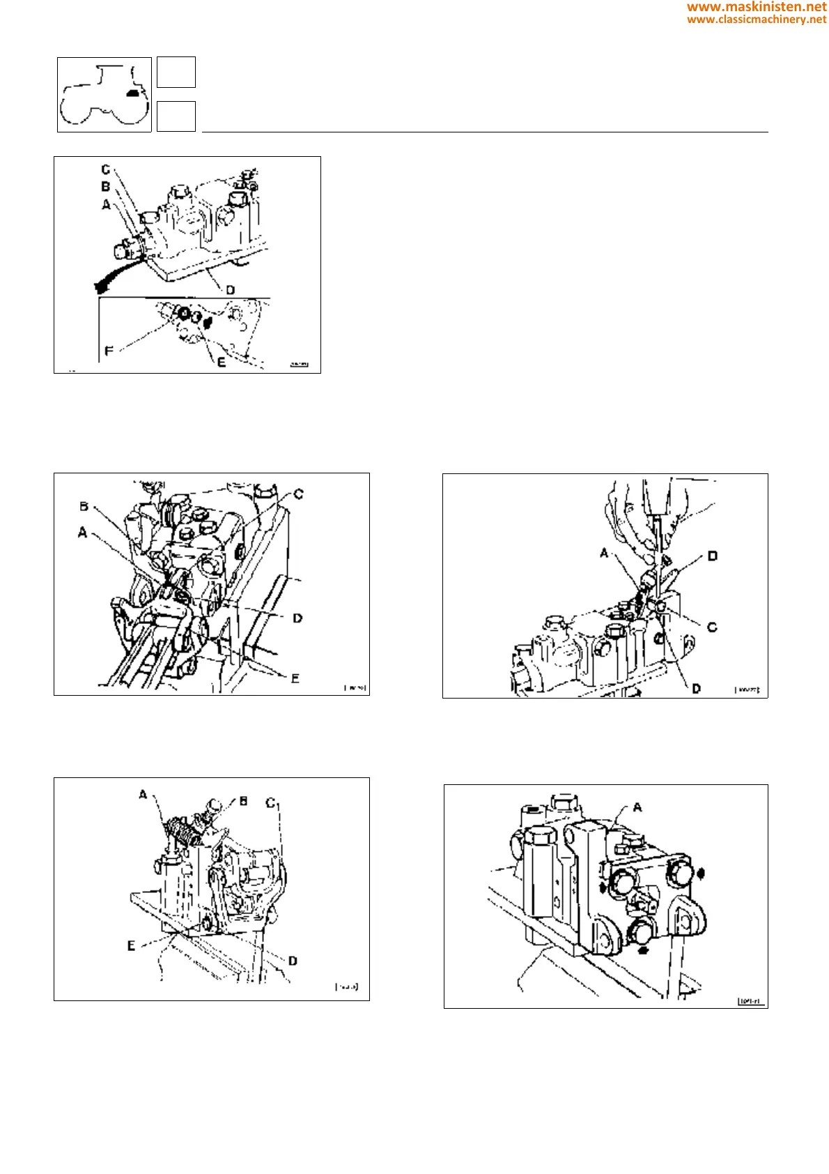
Fig. 17 - Hydraulic distributor seal ring.
A Anti-shock valve
B Gasket
C Fitting
D Plate
E Oil delivery hole to power-lift cylinder
F O-ring
Fig. 18 - Hydraulic distributor control levers.
A Spacer
B Plate
C Distributor stem
D Pin
E Lever assembly
Fig. 19 - Removing the ratchet return spring.
A Spring securing pin
B Springs
C Fork
D Snap ring
E Pin
Checking distributor when assembled - Fig. 17
Before taking the distributor to pieces perform the nonreturn valve
tightness test operating as follows:
1. Fit O-ring F into hole E groove as shown in figure and then
secure plate D underneath the distributor using two bolts, so that
hole E be thoroughly sealed.
2. Loosen anti-shock valve A holding fitting C locked with a
spanner. Remove the valve along with underlying gasket B.
3. Connect hydraulic pump no. 5.9030.520.4 to fitting C; Press-
urize the oil through the pump and make sure no oil leaks from the
distributor.
4. Should any leaks be noticed, this could be caused by the poor
nonreturn valve efficiency. For this reason the hydraulic distributor
shall be completely overhauled.
Fig. 20 - Removing the distributor ratchet return spring.
A Spring
B Limit lever
C Pin
D Pin
Fig. 21 - Hydraulic distributor control mechanism support.
A Lever support
59
5
vehicle
rear hydraulic power-lift
274
www.maskinisten.net
www.classicmachinery.net