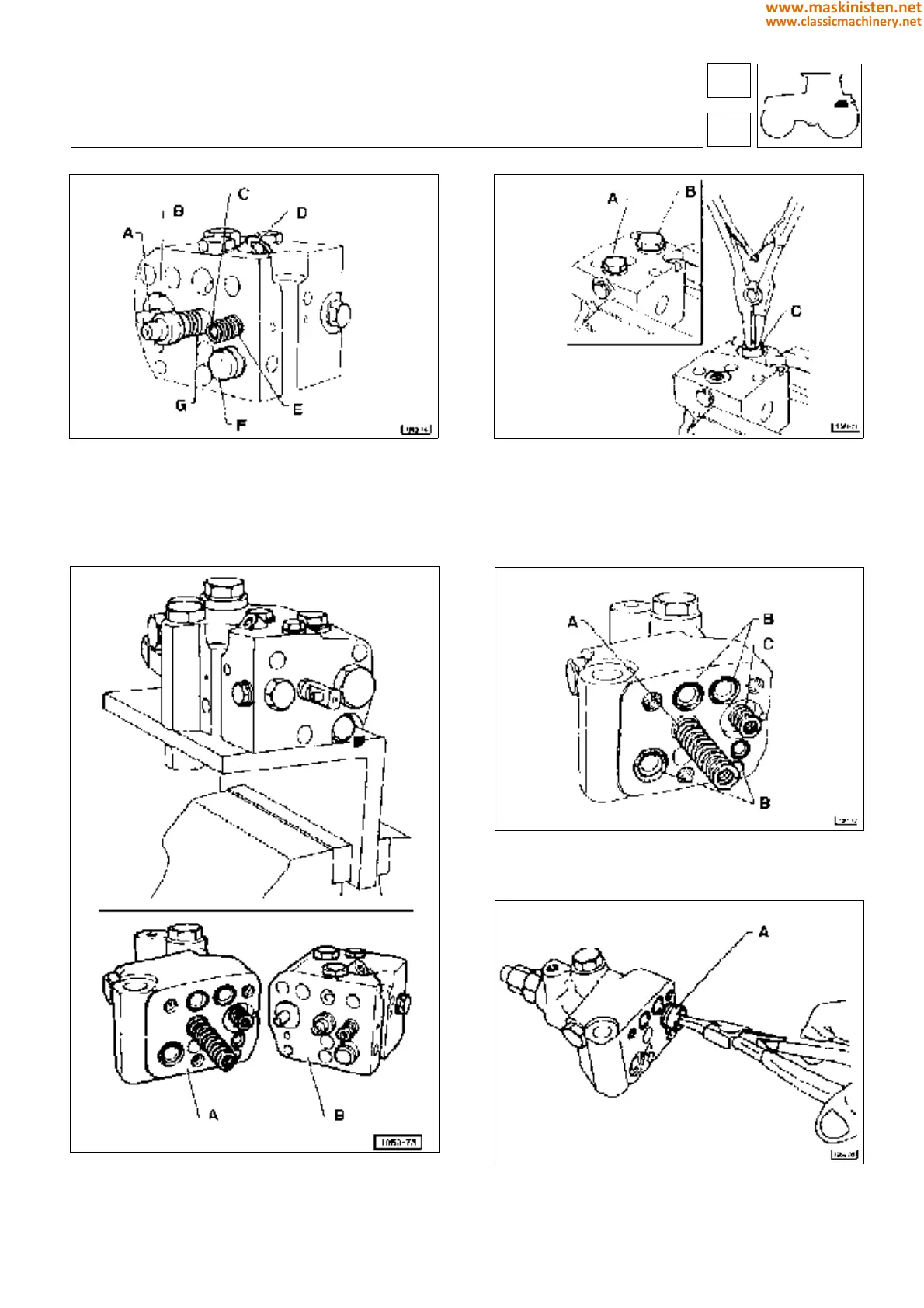
Fig. 22 - Hydraulic distributor case.
A Nonreturn valve pushrod
B Plate
C Spacer
D Oil inlet valve
E Pilot/Control valve spring
F Oil flow control valve piston
G Hydraulic distributor stem
Fig. 23 - Stripping the hydraulic distributor.
A Front case
B Rear case
Fig. 26 - Hydraulic distributor, front portion.
A Nonreturn valve piston
Fig. 24 - Disassembling the nonreturn valve.
A Pilot/Control valve cap screw
B Nonreturn valve cap screw
C Nonreturn valve
Fig. 25 - Disassembling the springs and the sealing rings.
A Hydraulic distributor spring
B O-ring
C Spring
59
5
vehicle
rear hydraulic power-lift
275
www.maskinisten.net
www.classicmachinery.net