Charging the system
with recharging station p/n 5.9030.508.6
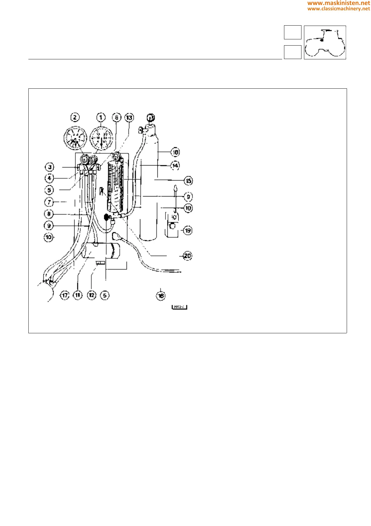
Fig. 4 - Charging station for air conditioning circuit.
Filling the metering unit
Connect the refrigerant bottle to the metering unit by means of the high or low pressure hose (9 - 10, Fig. 4).
Make certain that the valve (5, Fig. 4) is securely shut, then open the valve of the bottle.
As the refrigerant flows into the metering unit, open and shut the air bleed valve (14, Fig. 4) intermittently.
Read the value given by the hand of the metering unit pressure gauge (13, Fig. 4) and position the value against the
indicator.
Once 1800 grams of refrigerant have been transferred into the metering unit, close the valve of the bottle and detach
the hose.
Refilling the system with oil
Connect the high pressure hose (9, Fig. 4) of the recharge station by way of the smaller diameter valve A (Fig. 4/a) positioned
on the pipeline connecting with fitting D (Fig. 2) at the compressor (mounted in the engine compartment), and the low
pressure hose (10, Fig. 4) of the station by way of the larger diameter valve B (Fig. 4/a) positioned on the pipeline connected
with fitting S (Fig. 2) at the compressor; then activate the pump for 30 minutes approx to establish a vacuum in the circuit.
The valves (3 - 4 - 5 - 6, Fig. 4) must remain open during this operation.
systems
air conditioning
1 High pressure gauge
2 Low pressure gauge
3 Low pressure valve
4 Vacuum pump valve
5 Metering pipeline valve
6 Recharge pipeline valve
7 Metering pipeline
8 Vacuum pump pipeline
9 Low pressure circuit recharge pipeline (blue)
10 High pressure circuit recharge pipeline (red)
11 Vacuum pump
12 Electric switch
13 Metering gauge
14 Air bleed valves
15 Metering unit
16 Electrical power supply
17 Compressor
18 Refrigerant bottle
19 Electric leak detector
20 Electric heater element for refrigerant
86
8
369
www.maskinisten.net
www.classicmachinery.net