20 BioPAT
®
Trace | Multi Trace Operating Instructions
BioPAT
®
Trace | Multi Trace Product Description
Adjusting the PID Controller
The principle of the PID controller is known since 1922 (Minorsky[1]), but
useful rules for adjustment were not available before 1942 (Ziegler and
Nicols[2]). Today most of the controller will be adjusted by empirical design.
This design can also be used in the field of biotechnology.
Literature
[1] Minorsky, Nicolas: Directional stability of automatically steered bodies;
J. Amer. Soc of Naval Engineers 34 (1922), pp. 280–309.
[2] Ziegler, J.G. and Nicols, N.B.: Optimum settings for automatic controllers;
Trans. ASME, 64 (1942), pp. 759-768
3.4 Data Transmission and Data Saving
The BioPAT
®
Trace | Multi Trace has a number of outputs, making integration
into data recording systems very flexible. Along with a standard analog output
for signal ranges from 0 to 20 mA, 0 to 10 V or 4 to 20 mA, the BioPAT
®
Trace|
Multi Trace also features an Ethernet connection that connects the device to
a PC via a network. Using the software supplied, the measured results can be
visualized graphically and saved (see Chapter "8 Operation", page 75).
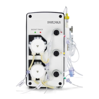
3.5 Equipment Supplied with the BioPAT
®
Trace | Multi Trace
Description Order no.
Device BioPAT
®
Trace with power adapter, power plugs
(Europe, USA, UK), cross-over Ethernet cable, operating
instructions and PC software (trace_mon)
BPT0001
Device BioPAT
®
Trace with power adapter, power plugs
(Europe, USA, UK), cross-over Ethernet cable, operating
instructions and PC software (trace_mon)
BPT00M
 Loading...