28 BioPAT
®
Trace | Multi Trace Operating Instructions
Design and Function
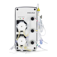
Rear view of the device with the following elements:
Figure 8 shows the rear view of the BioPAT
®
Trace | Multi Trace. The device
can be switched on and off by pressing the On/off switch(9). Using the
calibration data, the electrochemical signal of the biosensor is converted
internally to a concentration value. The measured value is output after the
analysis is completed on a PC interfaced to the Ethernet connection(10).
Optionally, the signals can be output via the analog signal outputs(12). The
following ranges are possible: 0..10V, 0..20mA, 4..20mA. The USB interface
(11) and the serial interface (RS232 port) (13) can also be used for data transfer
(currently not implemented).
12a
12b
12c
13
11
10
9
Fig. 8: Connections
Pos. Function Pos. Function
9 On/off switch 12 a | b | c Analog outputs (1–3)
10 Ethernet connection 13 Serial interface
11 USB interface
 Loading...