Hardware Manual for the PCD2.M5 Series│Document 26/856; Version EN 12│2014-07-24
Saia-Burgess Controls AG Communication interfaces
5
5-18
Serial interfaces on I/O module slots 0 - 3
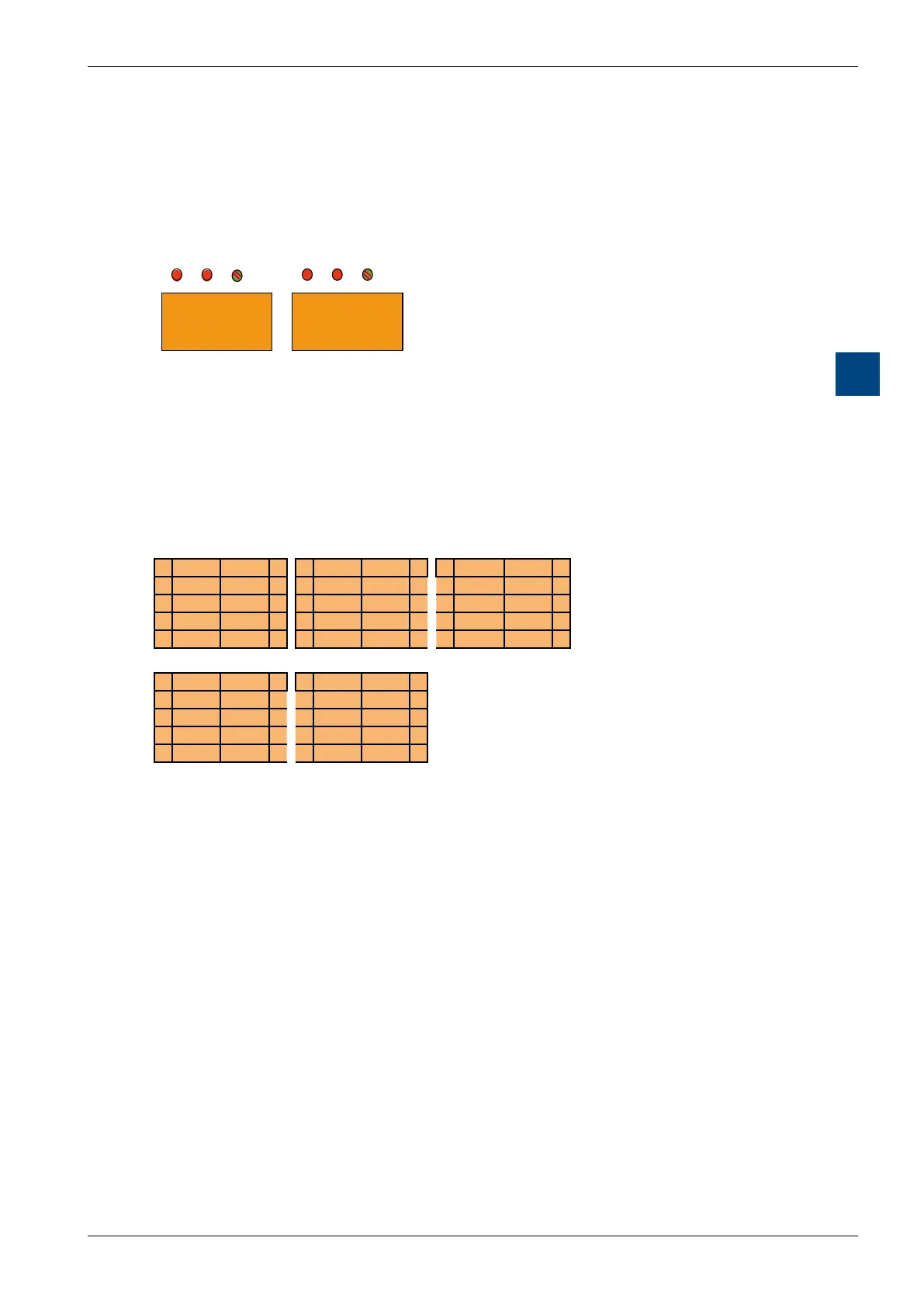
Connections and LEDs
x.1
x.0
LED TxD x.1
LED RxD x.1
LED Status x.1
LED TxD x.0
LED RxD x.0
LED Status x.0
Terminal x.1
10 polig (2x5)
Terminal x.0
10 polig (2x5)
Switch for network
termination
Port x.0
(RS485)
on board
PCD2.F2xxx
Summary of connections
RS-232 RS-422 RS-485
0 PGND TxD 1 0 PGND Tx 1 0 PGND Rx-Tx 1
2 RxD RTS 3 2 /Tx Rx 3 2 /Rx-/Tx 3
4 CTS PGND 5 4 /Rx PGND 5 4 PGND 5
6 DTR DSR 7 6 RTS /RTS 7 6 7
8 COM DCD 9 8 CTS /CTS 9 8 (SGD) 9
TTY(CL) Belimo MP bus
0 PGND TS 1 0 PGND MP 1
2 RS TA 3 2 ‚MFT‛ ‚IN‛ 3
4 RA PGND 5 4 PGND 5
6 TC RC 7 6 7
8 TG RG 9 8 9
Spring terminal block (supplied)
Eachserialporthasitsownindividual10-polespringterminalblock.TheF2xx
moduleisttedwithtwospringterminalblocks,theright-handoneforPortx.0and
the left for Port x.1.
Maximum wire gauge: 1.0 mm
2
AWG 18
LEDs
LED TxD: Send data detection
LED RxD: Receive data detection
LED status: The "Status" LED displays the status of the serial port,
‘green’ means that the port is working properly
● BothLEDspermanentlyred: F2xxxnotrunning
● BothLEDsgreen25%/red75%: F2xxxstart-upprocedure
● BothLEDsgreen50%/red50%: F2xxxrunning,butnocommunicationwith
PCD2.M5_
● StatusLEDgreen75%/red25%: F2xxxrunning,Interfacestillnot
assigned by the program
● StatusLEDgreen100%: F2xxxrunning,Interfaceassigned