Page 20 of 86 SCHÄFER IT-Systems
Industriestraße 41 D-57518 Betzdorf
Phone: +49 (0) 2741/283-770 sales@schaefer-it-systems.de www.schaefer-it-systems.de As
amended on 16/8/2019 (subject to technical changes)
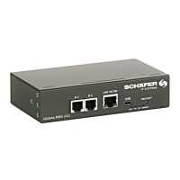
Connect the antenna cable to the modem PCB. Carefully
connect the U-FL antenna cable to the U-FL input and gently
push it onto the contact.
Unscrew the nut and washer from the antenna cable.
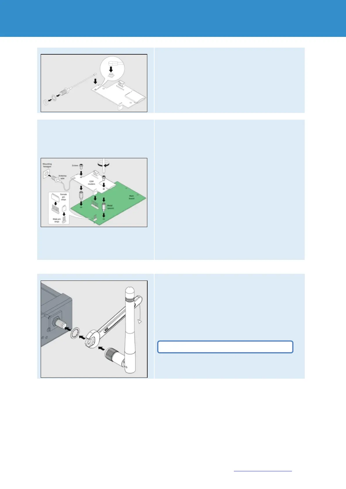
The motherboard should already be equipped with two metal
spacers. If this is not the case, please request this from the
manufacturer.
Place the GSM modem over the metal spacers and pin strips
on the motherboard. Push the GSM card carefully down so
that:
Pin strip on the motherboard (3-pin) is plugged into the socket
strip on the GSM PCB (3-pin).
Pin strip on the motherboard (7-pin) is plugged into the socket
strip on the GSM PCB (7-pin).
Two holes on the GSM PCB are located directly above the
metal spacers and the GSM board touches the metal spacers.
Screw two M3 screws supplied with the modem through the
holes in the metal spacers as shown in the figure.
Insert the antenna wire into the hexagonal mounting hole on
the front or rear of the device (e.g. RMS 442 has only one
front hole SMA).
The antenna wire should now protrude forwards or backwards
(e.g. RMS 442 has a front hole), as shown in the figure.
Place the washer on the end of the antenna wire thread.
Screw the nut onto the antenna wire thread manually until it
stops.
Tighten the nut with a spanner.
Screw the antenna at the end of the antenna wire thread.
Do not overtighten the nut on the thread!
 Loading...