Page 30 of 86 SCHÄFER IT-Systems
Industriestraße 41 D-57518 Betzdorf
Phone: +49 (0) 2741/283-770 sales@schaefer-it-systems.de www.schaefer-it-systems.de As
amended on 16/8/2019 (subject to technical changes)
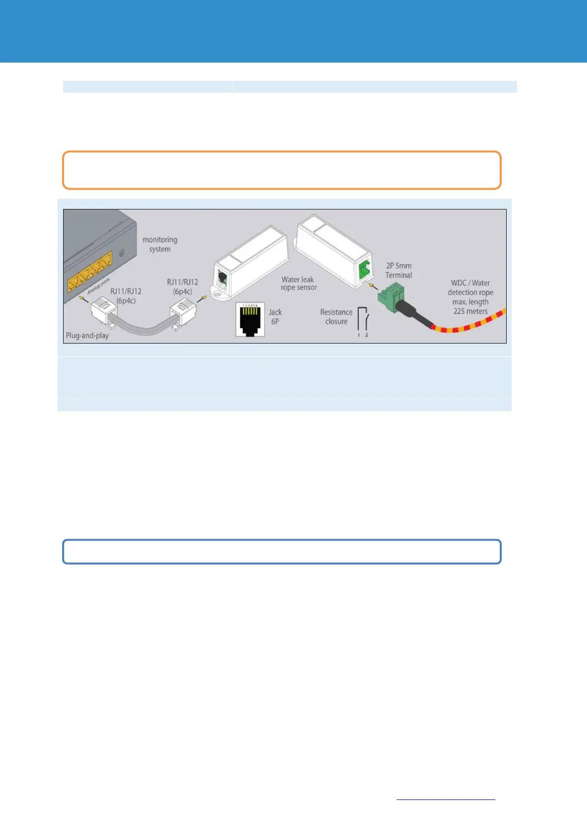
1x for connection of a leak cable 50.25 or 10
4.5.1. Installation
5. CAN sensors and extensions
Connect CAN devices to any port CAN1 or CAN2 on the monitoring system using the corresponding cable
supplied.
CAN sensors can also be connected to the port of another CAN sensor or another CAN unit that is connected to the
CAN bus. The devices and their connection are determined via the web interface on the rack monitoring system.
The dip switch "TR" should be switched to "ON" for the last sensor on each bus "CAN 1" and "CAN 2".
See section "TR" below. See section “TR” further below.
1. The module is connected to a free sensor port on the RMS or a sensor extension unit and detected
automatically by the system.
2. Wrap the water leak cable around or under potential leaks to detect leaks.
To install extensions, switch the device off, disconnect it from the socket or at the voltage input.
You can connect up to a maximum of 8 CAN sensors and CAN devices to one CAN bus.