Page 34 of 86 SCHÄFER IT-Systems
Industriestraße 41 D-57518 Betzdorf
Phone: +49 (0) 2741/283-770 sales@schaefer-it-systems.de www.schaefer-it-systems.de As
amended on 16/8/2019 (subject to technical changes)
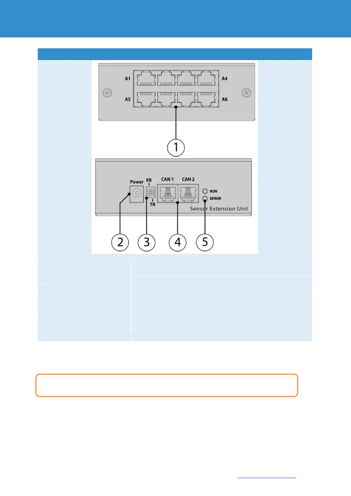
Connections extension unit
8x RJ12 analogue & digital sensor inputs with auto-sensing
for connecting an external power supply 12V
Termination switch at the end of a CAN chain
Memory switch for reprogramming the module
"CAN" - digital connector RJ12 for connection to the master module, CAN
sensors or CAN extensions
a CAN bus, with auto-sensing.
shows the connection status of the device to the main module
"ERR" - indicates that the device has lost the connection to the main
module
5.2.1. Installation
There are two mounting holes on the bottom of the device for mounting on a top hat rail.
There are 4 additional mounting holes on the side for mounting in 19 “with optional mounting
accessories.
To install extensions, switch the device off, disconnect it from the socket or at the voltage input.