Page 45 of 86 SCHÄFER IT-Systems
Industriestraße 41 D-57518 Betzdorf
Phone: +49 (0) 2741/283-770 sales@schaefer-it-systems.de www.schaefer-it-systems.de As
amended on 16/8/2019 (subject to technical changes)
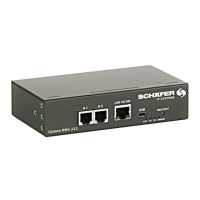
5.5. pir – vibr. – temp. probe
"CAN" - digital connector RJ12 for connection to the master module, CAN
sensors or CAN extensions
a CAN bus, with auto-sensing.
Termination switch at the end of a CAN chain
"Green" - indicates "connected" status with the main module, "Red" -
indicates "not connected" status, "Orange" - indicates "alarm" status.
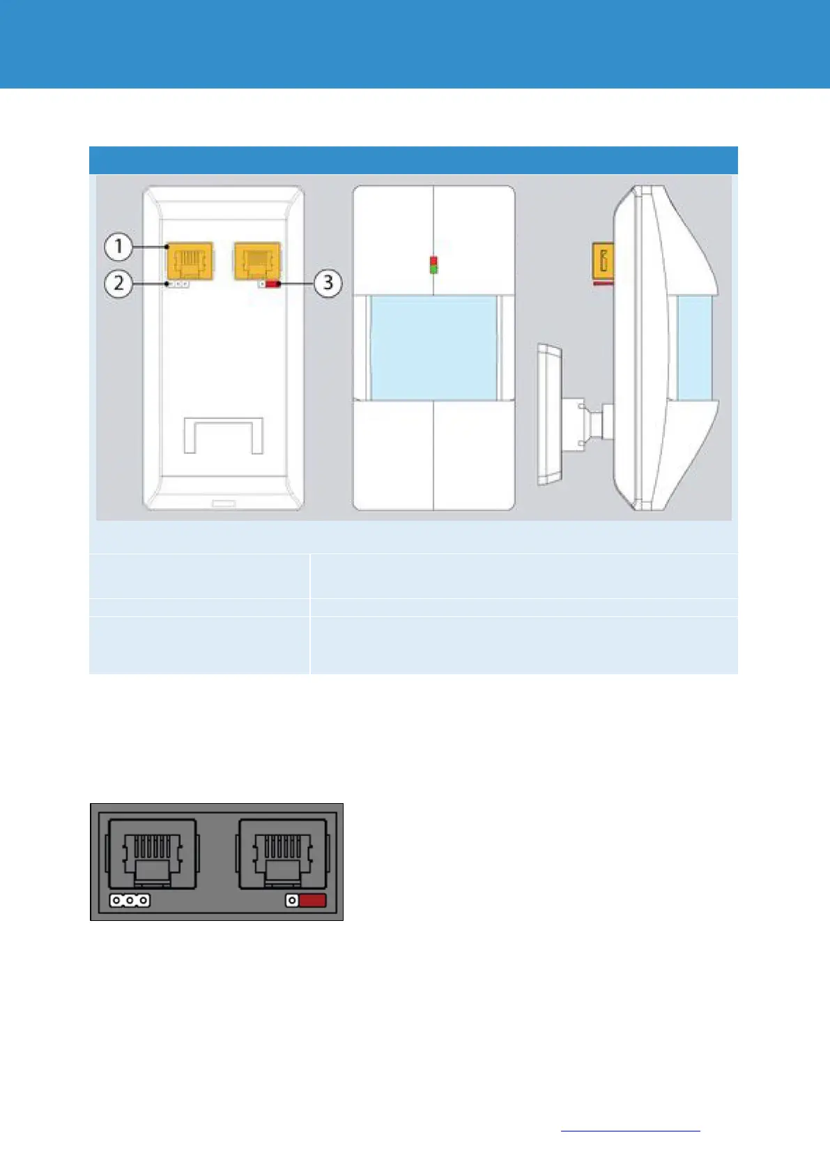
5.5.1. Sensor connection:
Jumpers must be set as follows:
a) For all sensors except the last sensor in the chain the jumpers on 1 and 2 . TR are ON.