Page 36 of 86 SCHÄFER IT-Systems
Industriestraße 41 D-57518 Betzdorf
Phone: +49 (0) 2741/283-770 sales@schaefer-it-systems.de www.schaefer-it-systems.de As
amended on 16/8/2019 (subject to technical changes)
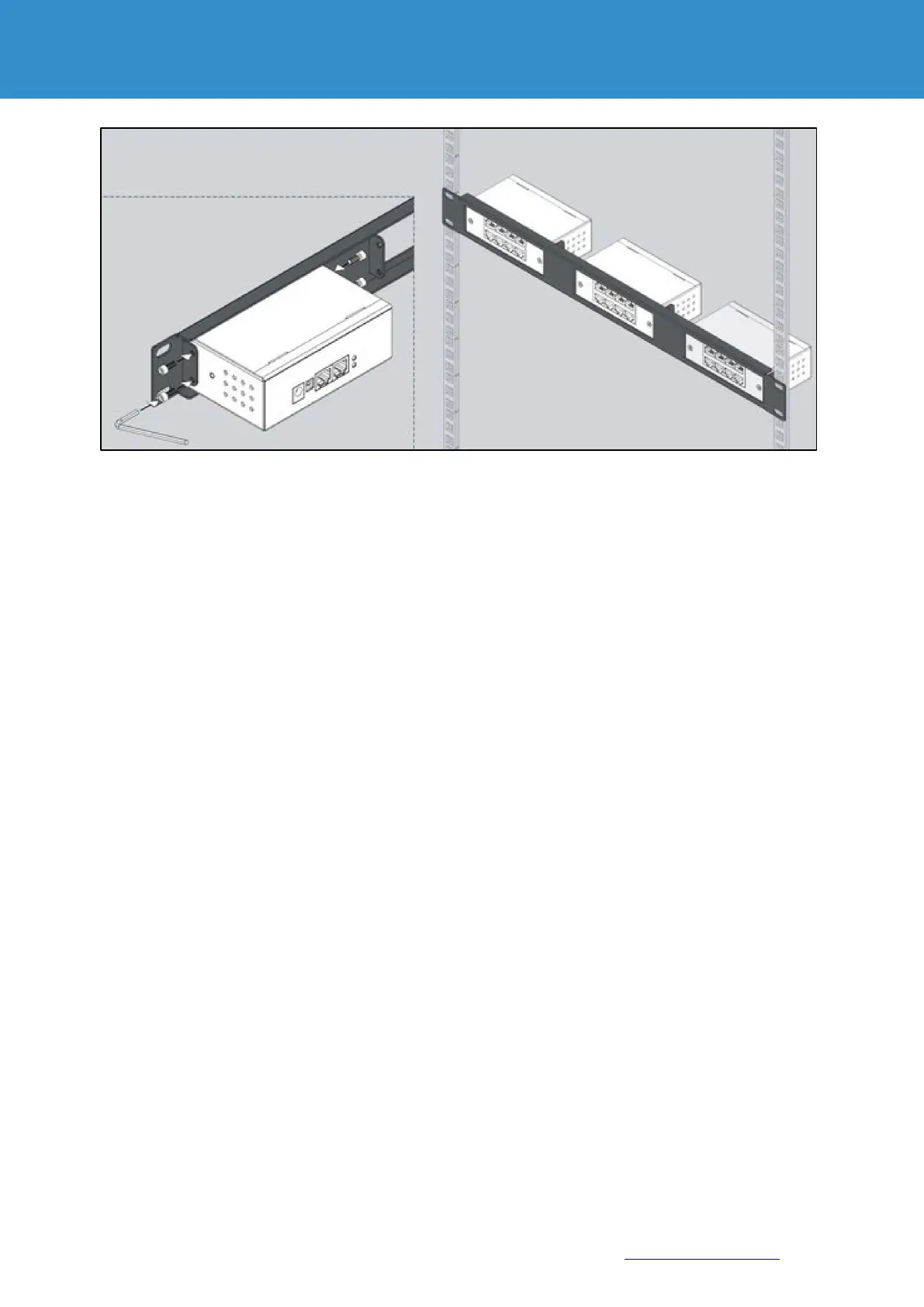
Connect the CAN input of the device with the RJ11 / RJ12 cable that is connected to the CAN input of
the previous CAN device or monitoring system.
The red LED lights up. Adjust the TR bus terminations on the connected CAN devices. CAN bus
terminations TR should only be in the ON state at the end of the CAN device port and in the OFF state
for all intermediate devices (1,2).
A CAN bus cannot have more than 8 CAN units, sensors and / or other CAN devices.
Usually an external 12V 0.5A power supply is connected to the socket marked PWR.
If only one extension unit is connected to the monitoring, it can be supplied with voltage at a distance of
up to 10 m via the CAN bus.
In all other cases, the use of an external power supply is necessary.