126 User’s Manual
9 Schematics
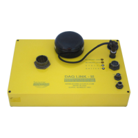
9.1 DAQlink III Connector wiring
LED’s
Network – Illuminates when Ethernet Network is connected
Network Data –Illuminates when Network Data is detected
Status –
Green – waiting for trigger
Amber – Recording data
Battery
Flashing Green – Battery is Good (Above 12 volts)
Flashing Amber – Battery is low (battery 10 volts to 12 volts)
Flashing Red – Battery is very low (battery is less than 10 volts)
3 pin trigger Connector
A– TB active – A
B– TB return (GND) – B
C- +12 volt through 5 Kohm resistors
When DAQlink III trigger option is set to trigger on Time Break, then this input is used
to trigger the box. This input drives an opamp input and the trigger level is set by software.
Normal trigger level is 2 volts minimum to trigger. Positive Voltage should be applied to pin A,
and negative voltage to pin B. Maximum voltage should be less than 60 volts.
When using the ST-01 trigger switch, connect Pin A to Pin C and to the High voltage side
of the ST-01 switch. Connect pin B to the Low voltage side of the ST-01 switch.
19 pin Aux/ GPS Connector (PT07-14-19S)
A - +Battery
E- RS232 Receive
F – PPS pulse
G– GND
An external GPS receiver can be connected to the 19 pin GPS connector using a PT06A-
14-19P. The GPS receiver must be setup for:
• 19200 baud
• $GPGGA and $GPRMC messages only
Power 2pin MS to X9 connector
A – Positive battery – A
B – Negative battery - B
. There are two internal fuses on the board to prevent damage to the unit. However, we
still recommend using an external fast blow fuse of 2 amps. The unit can be powered from any
DC source supplying a minimum of 10 VDC to a maximum of 18VDC.
Ethernet – 10 base T
Standard Patch cable to Computer