© 2019 Safe Fleet | All rights reserved | Part #: 700-1123 R4
p. 21
TH8 Installation and Conguration Guide
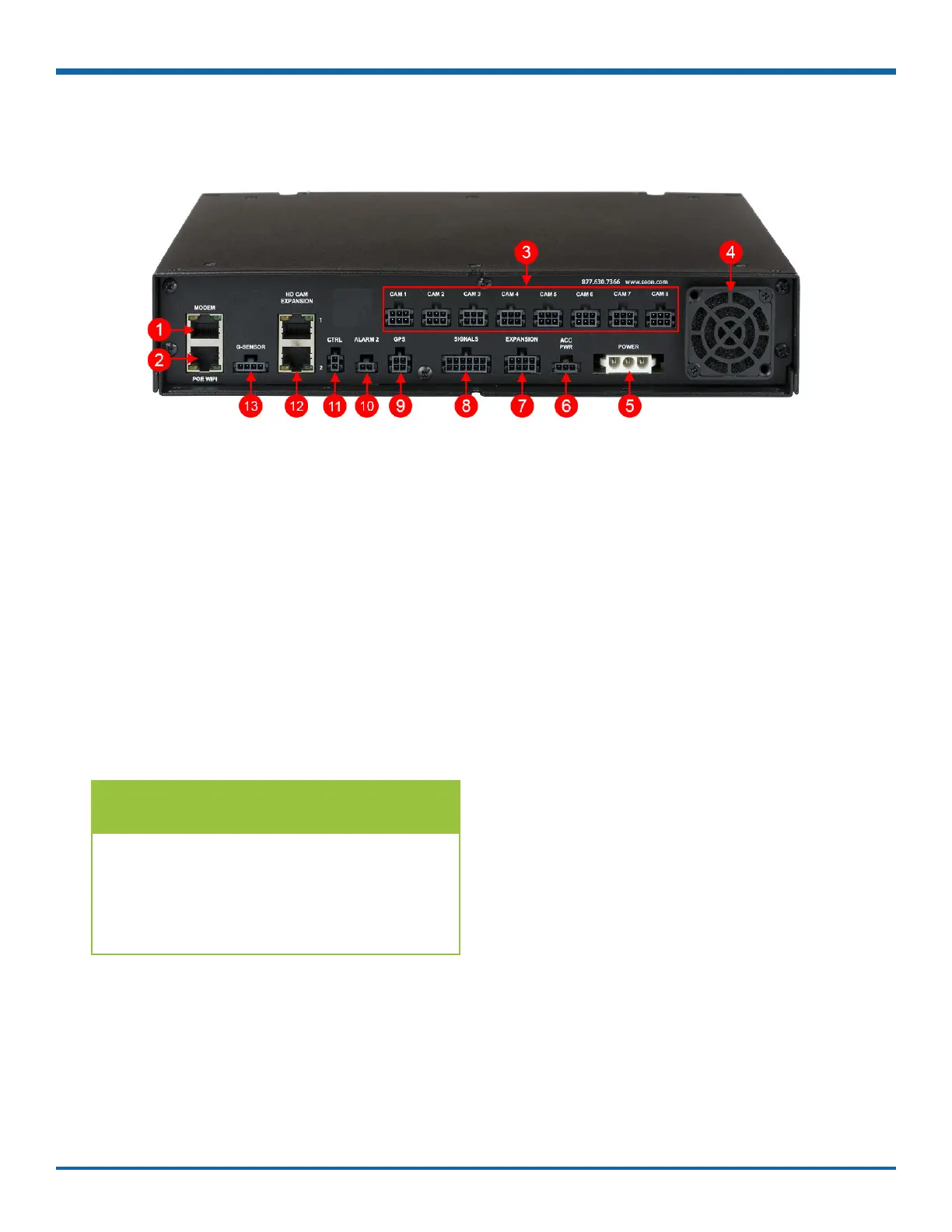
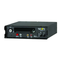
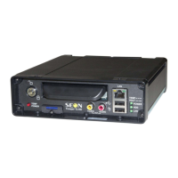
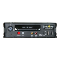
DVR Back Panel Features
1. MODEM - RJ-45 Ethernet LAN connector for a
laptop, Smart-Reach Mobile wireless equipment,
or other accessories
2. POE WIFI - dedicated Ethernet port for
connectivity with Smart-Reach Lite wireless
bridge and other equipment.
3. CAM 1 to CAM 8 - input connectors (6-pin) for
eight cameras
4. Fan - intake fan
5. POWER - input for power harness
6. ACC PWR - output connector for powering
accessories, including an optional Power over
Ethernet (POE) injector kit
7. EXPANSION - connector for communicating with
other devices
8. SIGNALS - connector for signal harness, with an
optional adapter for the diagnostic indicator
9. GPS - input connector for GPS receiver
10. ALARM 2 - additional alarm input for the alarm
button or covert trigger
11. CTRL - control connector for accessories
12. HD CAM EXPANSION 1 & 2 - RJ-45 connectors
for 2 IP cameras, or 1 IP camera and a
companion DVR (for example, a TH4C).
13. G-SENSOR - input for optional G-force sensor
unit
TIP: POE WIFI Port is 12-volt
In addition to the data transmitted, the
POE WIFI port supplies 12 volts to power
accessories such as the Smart-Reach Lite
wireless bridge.