MX-2300/2700 N/G SIMULATION 7 – 21
22-4
Purpose : Adjustment/Setup/Operation data check
Function (Purpose) : Used to check the trouble (self diag) his-
tory.
Section :—
Item : Trouble
Operation/Procedure
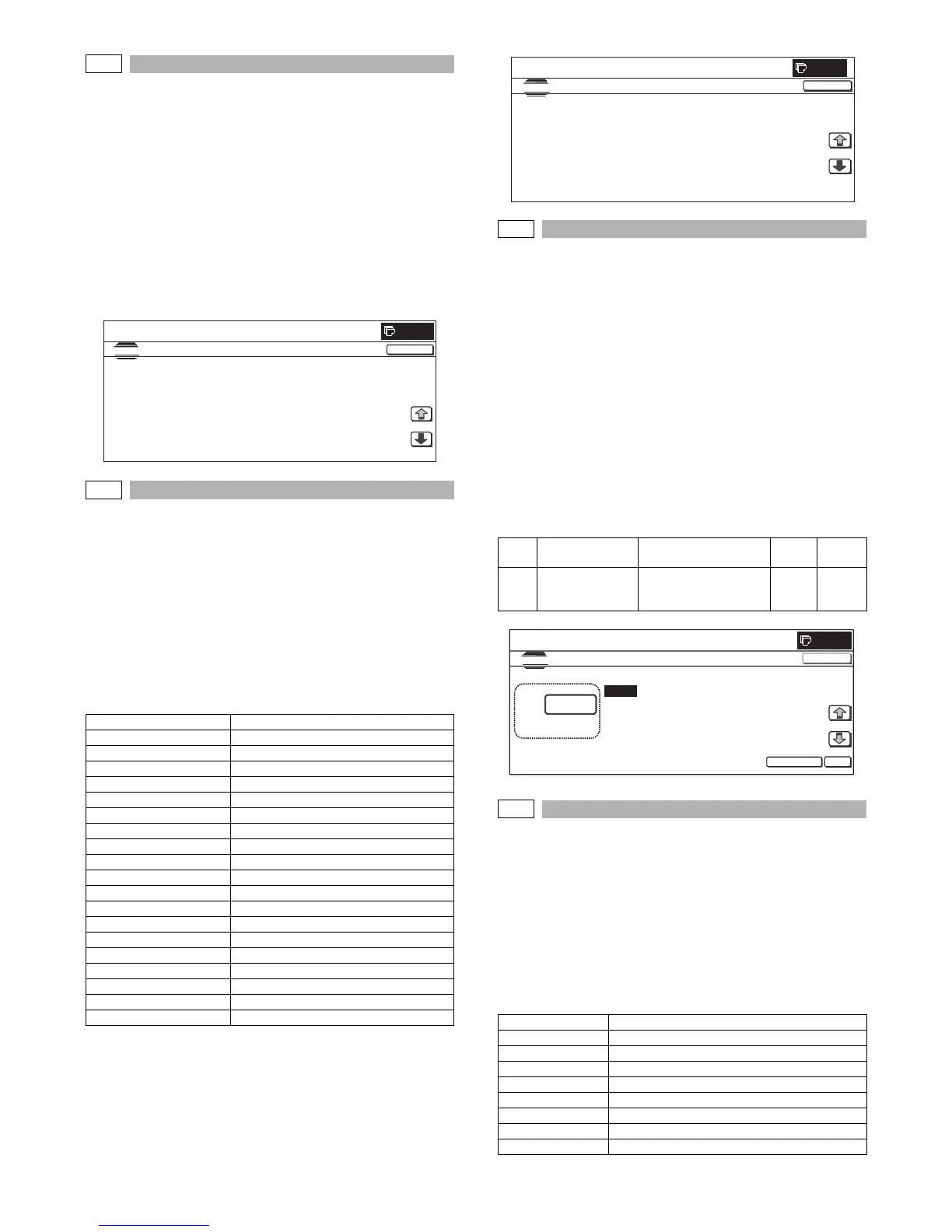
The trouble history is displayed.
The trouble history is displayed sequentially from the latest one.
The max. 30 items can be stored. (The oldest one is deleted
sequentially.)
Press [COLOR] or [BLACK] button to print.
* Trouble code list: Refer to "2. Trouble code list" in the "[8] SELF
DIAG AND TROUBLE CODE".
22-5
Purpose : Others
Function (Purpose) : Used to check the ROM version of each
unit (section).
Section :—
Item : Software
Operation/Procedure
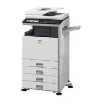
The ROM version can be checked with [↑] [↓] buttons.
When there is any problem in the software, use this simulation to
check the ROM version of each section and revise the version if
necessary.
Press [COLOR] or [BLACK] button to print.
22-6
Purpose : Adjustment/Setup/Operation data check
Function (Purpose) : Used to output the list of the setting and
adjustment data (simulations, FAX soft
switch, counters).
Section :—
Item : Data (Setting, adjustment data)
Operation/Procedure
* When installing or servicing, this simulation is executed to print
the adjustment data and set data for use in the next servicing.
(Memory trouble, PWB replacement, etc.)
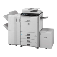
1) Select the print mode with 10-key.
2) Press [EXECUTE] button.
The list print selected in step 1) is started.
* When [C] key, [CA] key, [SYSTEM SETTINGS] key, or [EXE-
CUTE] button is pressed during printing, the operation is ter-
minated.
22-8
Purpose : Adjustment/Setup/Operation data check
Function (Purpose) : Used to check the number of use of the fin-
isher, the RSPF, and the scan (reading)
unit.
Section :—
Item : Counter
Operation/Procedure
The values of the finisher counter, the RSPF counter, and the scan-
ner (read) related counters are displayed.
Press [COLOR] or [BLACK] button to print.
S/N Serial No.
ICU(MAIN) ICU (Main section)
ICU(BOOT) ICU (Boot section)
LANGUAGE Language support data version
GRAPHIC Graphic data for LCD
IMG DATA ROM ImageASIC FlashROM data
COLOR PROFILE Color profile
PCU PCU
SCU SCU
SPF SPF
FAX1(MAIN) FAX1 line (Main section)
FAX2(MAIN) FAX2 line (Main section)
DESK Desk unit
LCC Side LCC
FINISHER Finisher
SADDLE Saddle unit
PUNCH Punch unit
NIC NIC
POWER-CON Power controller
E-MANUAL Operation manual (HDD storage)
0
CLOSE
TROUBLE CODE DATA DISPLAY
SIMULATION NO.22-04
TEST
1/2
E7-23 F9-20 F2-39 L4-31
F1-50 L4-02 F2-39 F1-50
F1-50 L4-02 F1-61 F1-50
F1-50 F2-39 H5-01 E7-23
U5-12 F2-39 L1-00 E7-23
Item
Display item &
detail display
Description
Set
range
Default
value
A DATA PATTERN Data pattern selection
1: List print
2: List print (Sim50-24)
1 to 2 1
RSPF/DSPF Document feed quantity
SCAN Number of scan
STAPLER Staple counter
PUNCHER Puncher counter
STAMP Stamp counter
SADDLE STAPLER Saddle staple counter
OC_OPEN OC open/close counter
RSPF/DSPF_OPEN RSPF/DSPF open/close counter
OC LAMP_TIME Total lighting time of the lamp in OC section
SIMULATION NO.22-05
S/N : **********
TEST
CLOSE
0
ICU(MAIN) : 00.00.00
ICU(BOOT) : 00.00.00
LANGUAGE : 00.00.00
GRAPHIC : 00.00.00
IMG DATA ROM : 00.00.00
COLOR PROFILE : 00.00.00
PCU : 00.00.00
SCU : 00.00.00
SPF : NONE
FAX1(MAIN) : NONE
1/2
0
A:
A: 1
; DATA PATTERN
SIMULATION NO.22-06
DATA PRINT MODE
1
[1~2]
OK
TEST
EXECUTE
CLOSE