MX-2300/2700 N/G SIMULATION 7 – 92
50-2
Purpose : Adjustment
Function (Purpose) : Used to adjust the copy image position on
print paper in the copy mode and to adjust
the void area (image loss). (Simple adjust-
ment)
(Similar to SIM50-01. This simulation pro-
vides the simpler method.)
Section :–
Item : Image quality (Image position)
Operation/Procedure
1) In advance to this adjustment, execute the magnification ratio
adjustment in the sub scanning direction (SIM48-01).
2) Select "TRAY"and set 0 to L1 and L2.
* L1 and L2 are changed to 0, the following adjustment values
are automatically set.
RRCA adjustment value: 50
RRCB adjustment value: 90
(Reference value 50 + paper lead 49 (4.9mm))
3) Place a ruler along the left edge of the document table, and
make a black copy in 400%.
4) Measure the distances L1 and L2 on the copied image in the
unit of 0.1mm, and multiple the distance values with 10, and
enter the obtained values. (Be sure to enter L1 and L2
together.)
• L1: Distance between the copy image lead edge position
and the scale of 10mm.
• L2: Distance between the paper lead edge and the copy
image lead edge position.
5) When [EXECUTE] button is pressed, the current entered value
is saved to EEPROM and RAM.
6) Make a black copy in 100%, and adjust the rear edge void.
* When [CLOSE] button is pressed, the display is shifted to the
copy basic screen of simulation.
* Copying can be performed also by pressing [COLOR]/[BLACK]
key.
<Set range and default value of each setup>
A to G:1step = 0.1mm
A. Document lead edge reference position: (L1), B. Paper lead
edge positions
Except for A and B, same as the item adjusted with SIM50-01.
The values adjusted with A and B are reflected to the document
lead edge reference position (RRC-A) and all the paper lead edge
positions (RRCB-**).
CLOSE
0
A:
A㧦 50
B㧦 50
C㧦 50
D㧦 50
㧧 RRCA
㧧 RRCB-CS12
㧧 RRCB-CS34
㧧 RRCB-LCC
SIMULA TION NO.50㧙01
LEAD EDGE ADJUSTMENT VALUE
50
0 99
OK
TEST
1
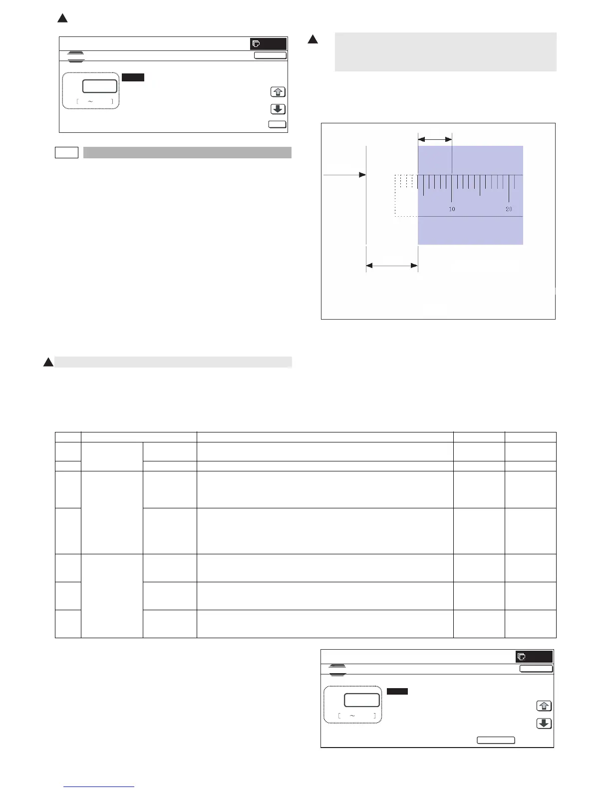
1
400% enlargement copy
Paper lead
edge
L1
L2
Fig. 1
Item Display item Description Set range Default value
A Actual measured
value
L1 Distance between the image lead edge and the scale of 10mm (Platen 400%,
unit of 0.1mm)
0 to 999 –
B L2 Distance between the paper lead edge and the image lead edge (unit of 0.1mm) 0 to 999 –
C Image loss
quantity set value
LEAD Lead edge image loss quantity setting
The lead edge image loss quantity is specified. Difference between the
document lead edge scan start position and the document lead edge
* The greater the value is, the greater the image loss is.
0 to 99 30
D SIDE Side image loss quantity setting
The side image loss (SIDE) is specified. (Document width – Document edge
scan range / 2
(The rear edge image loss quantity is fixed to 0. (Without adjustment))
* The greater the value is, the greater the image loss is.
0 to 99 20
E Void quantity
setting
DENA Print lead edge adjustment
The void quantity at the paper lead edge is specified.
* The greater the value is, the greater the void is.
1 to 99 30
F DENB Sub scanning direction print range adjustment
The void quantity at the paper rear edge is specified.
* The greater the value is, the greater the void is.
1 to 99 20
G FRONT/REAR FRONT/REAR void quantity adjustment
The void quantities at the left and right edges of paper are specified.
* The greater the value is, the greater the void is.
1 to 99 20
CLOSE
0
A:
A㧦 60
B㧦 0
C㧦 30
D㧦 15
㧧
L1
㧧
L2
㧧
LEAD
㧧
SIDE
SIMULATION NO.50-02
LEAD EDGE ADJUSTMENT VALUE(CALC)
60
0 999
TEST
EXECUTE
: Dec. 15 2005
1