MX-2300/2700 N/G SIMULATION 7 – 91
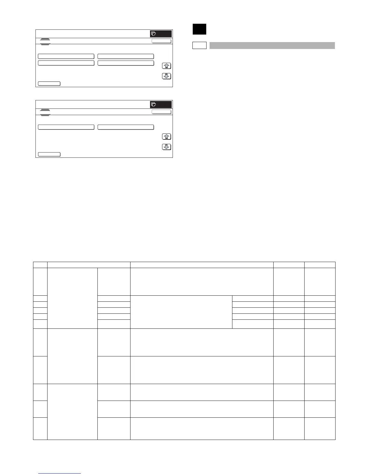
<Folder selection screen 1>
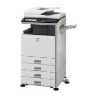
<Folder selection screen 2>
50
50-1
Purpose : Adjustment
Function (Purpose) : Used to adjust the copy image position on
print paper in the copy mode and to adjust
the void area (image loss). (The similar
adjustment can be executed with SIM50-05
and 50-02 (Simple method). (Document
table mode))
Section :—
Item : Image quality (Image position)
Operation/Procedure
1) Select the set item with [↑] and [↓] buttons.
The highlighted set value is switched and the value is dis-
played in the setting area.
* If there is any item over [↑], an active display is made and
item is shifted.
If there is no item over [↑], the display grays out and the
operation is invalid.
If there is any item under [↓], an active display is made and
item is shifted.
If there is no item over [↓], the display grays out and the
operation is invalid.
2) Enter the set value with 10-key.
* Press [C] key to clear the entered values.
3) When [OK], [↑], [↓] button, [COLOR], or [BLACK] key is
pressed, the current entered value is saved to EEPROM and
RAM.
* When [CLOSE] button is pressed, the display is shifted to
the copy basic screen of simulation.
* Copying can be performed also by pressing [COLOR]/
[BLACK] key.
<Set range and default value of each setup>
SIMULATION NO.49-03
TEST
E-MANUAL UPDATE/usbbd00
<DIR> FOLDER1
<DIR> FOLDER2
1/1
0
CLOSE
<DIR> FOLDER3
<DIR> MANUAL1
..
SIMULATION NO.49-03
TEST
E-MANUAL UPDATE/usbbd00
<DIR> MANUAL2
<DIR> MANUAL3
1/1
0
CLOSE
..
Item Display item Description Set range Default value
A Lead edge adjustment
value
RRCA Document lead edge reference position (OC)
The timing from start of document scan to recognition of the image lead
edge is adjusted. (0.1mm/step)
* The smaller the set value is, the faster the timing is. The greater the set
value is, the slower the timing is.
0 to 99 50
B RRCB-CS12 Resist motor ON timing adjustment
The timing to turn ON the resist roller from reception
of the resist signal is adjusted. (0.1mm/step)
* The smaller the set value is, the faster the timing
is. The greater the set value is, the slower the
timing is.
Standard cassette 1 to 99 50
C RRCB-CS34 Desk 1 to 99 50
D RRCB-LCC LCC 1 to 99 50
E RRCB-MFT Manual feed 1 to 99 50
F RRCB-ADU ADU 1 to 99 50
G Image loss quantity set
value
LEAD Lead edge image loss quantity setting
The lead edge image loss quantity is specified. The difference between the
document lead edge scan start position and the document lead edge
(0.1mm/step))
* The greater the value is, the grater the image loss is.
0 to 99 30
H SIDE Side image loss quantity setting
The side image loss quantity is specified. (Document width – Document
edge scan range) / 2 (0.1mm/step)
(The rear edge image loss quantity is fixed to 0. (Without adjustment))
* The greater the value is, the greater the image loss is.
0 to 99 20
I Void amount setting DENA Print lead edge adjustment
The void quantity formed at the paper lead edge is specified. (0.1mm/step)
* The greater the value is, the greater the void is.
1 to 99 30
J DENB Sub scan direction print range adjustment
The void quantity formed at the paper rear edge is specified. (0.1mm/step)
* The greater the value is, the greater the void is.
1 to 99 20
K FRONT/REAR FRONT/REAR void amount adjustment
The void quantities formed at the right and left edges are adjusted.
(0.1mm/step)
* The greater the value is, the greater the void is.
1 to 99 20