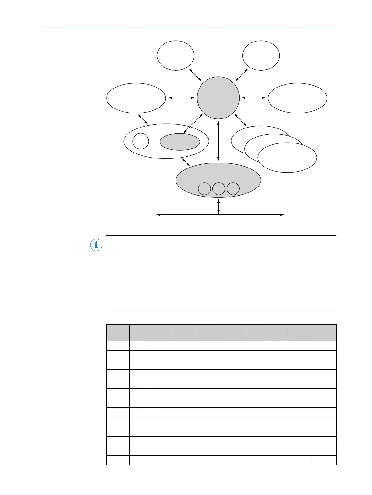
23h Position Sensor 01h Identity
04h Assembly
06h Connection Manager
F4h
F5h
Network
F6h
02h
Massage
Router
48h QoS 47h DLR
Config
Figure 12: Connections for the configuration assembly
NOTE
•
If the encoder is included as a generic module, then the configuration assembly
can be activated or not independently of the I/O assembly instances.
•
If the EDS file (electronic data sheet) of the encoder is used, then depending on
the instances of the I/O assembly, the configuration assembly is activated or not:
°
Active with instances 101, 102 and 103.
°
Not active with instances 101WS, 102WS, and 103WS.
•
When the configuration assembly is activated, it must not be empty. Otherwise,
the control may output an error.
Table 20: Data format of the configuration assembly attributes
Instanc
e
Byte Bit 7 Bit 6 Bit 5 Bit 4 Bit 3 Bit 2 Bit 1 Bit 0
100 0 Not used
1 Not used
2 Not used
3 Not used
4 Steps per revolution CPR (least significant byte)
5 CPR
6 CPR
7 CPR (most significant byte)
8 Total resolution CMR (least significant byte)
9 CMR
10 CMR
11 CMR (most significant byte)
12 Not used cw/ccw
1
3 PRODUCT DESCRIPTION
26
O P E R A T I N G I N S T R U C T I O N S | AFS/AFM60 EtherNet/IP 8014213/1EF3/2021-12-08 | SICK
Subject to change without notice

 Loading...


