Operating instructions Chapter 11
Flexi Classic
8011509/YPP0/2015-10-26 © SICK AG • Industrial Safety Systems • Germany • All rights reserved 97
Subject to change without notice
Technical specifications
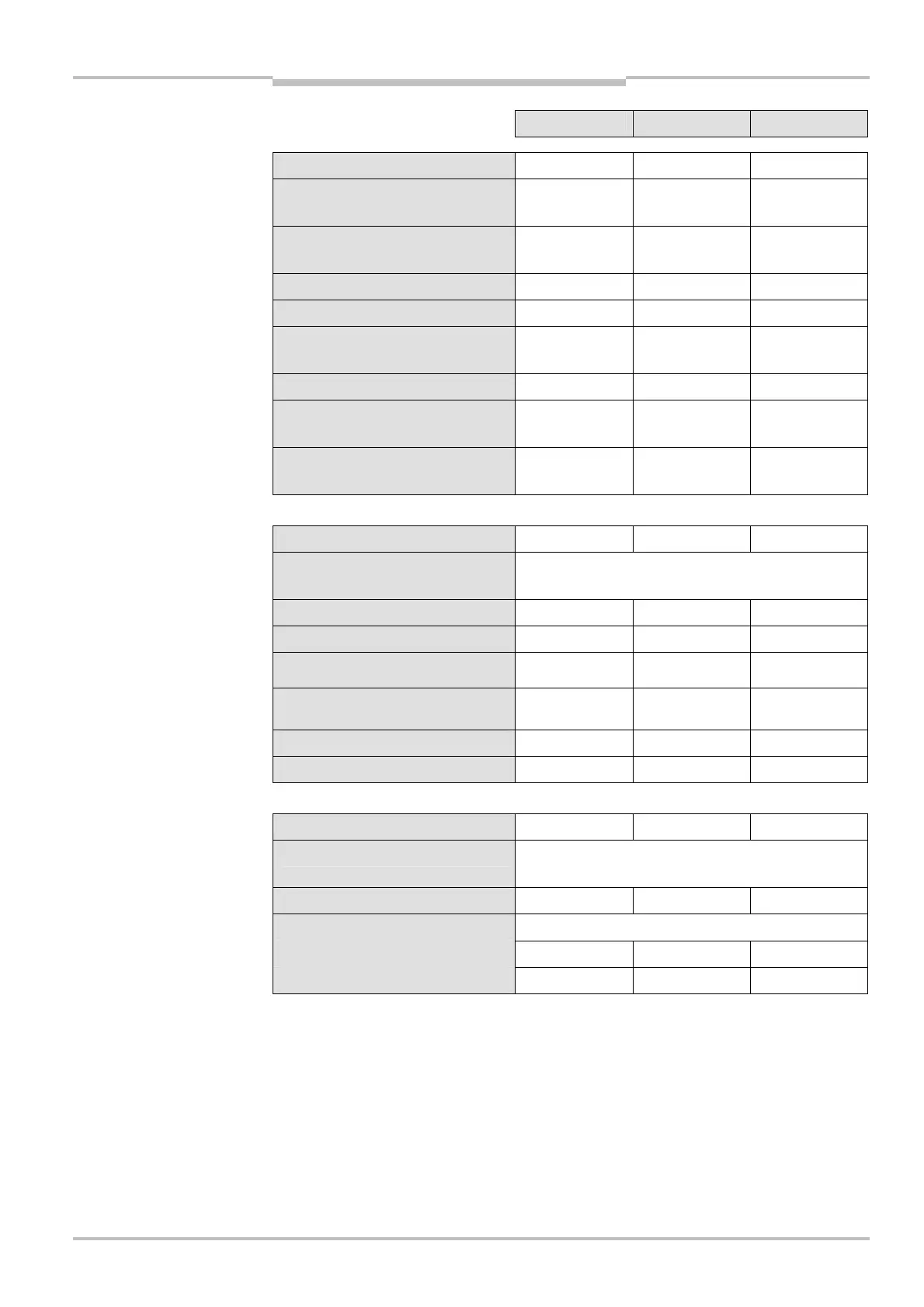
Minimum Typical Maximum
Power-up delay 70 ms – –
Synchronous time monitoring
program 1, 2
– 1500 ms –
Synchronous time monitoring
program 4 and 5
– 500 ms –
Muting ON program 3
11)
– – 61 ms
Muting OFF program 3 – 61 ms 165 ms
12)
Muting gap suppression
program 3
13)
95 ms – 100 ms
Reset time – – 124 ms
Teach-in time of ENTER button
UE410-MU (during power-up)
– – 3 s
Duration of actuation of the reset
button (only S1, S2)
50 ms – 5 s
Control outputs (X1, X2)
Number of outputs – – 2
Type of output
PNP semiconductors, short-circuit protected, cross-
circuit detecting
14)
Output voltage 16 V DC – 30 V DC
Output current
15)
– – 120 mA
Test period (X1, X2) program 1, 2,
4, 5, 6, 9
–
– 40 ms
Test period (X1, X2) program 3.2 –
–
X1 = 384 ms
X2 = 40 ms
Load capacity – – 1,000 nF
Cable resistance – – 100 Ω
Output circuit (Q1, Q2, Q3, Q4)
Number of outputs – 4 –
Type of output
PNP semiconductors, short-circuit protected, cross-
circuit detecting
14)
Switching voltage 18.4 V DC – 30 V DC
Switching current
I
Qn
, T
A
≤ 45 °C – – 2,0 A
I
Qn
, T
A
≤ 55 °C – – 1,6 A
11)
Time between muting condition valid (I3/I4 high) and muting possible.
12)
Max. switch-off time at muting error.
13)
One muting input (I3 or I4) may be LOW for the specified time.
14)
Cross circuit detecting only within a module.
15)
The total output current for a Flexi Classic system is limited. The current for supplying all sensors that are
connected to the UE410-MU/XU (X1/X2) and UE410-8DI (X1-X8) must be I < 600 mA and the current on a
Flexi Classic gateway must be I < 100 mA. If this total current is insufficient, please contact the SICK hotline.

 Loading...


