MAINTENANCE AND REPAIR 7
8026362 / V1-0/2022-03|SICK
Subject to change without notice
SUPPLEMENTARY OPERATING INSTRUCTIONS | VMS4100/5100
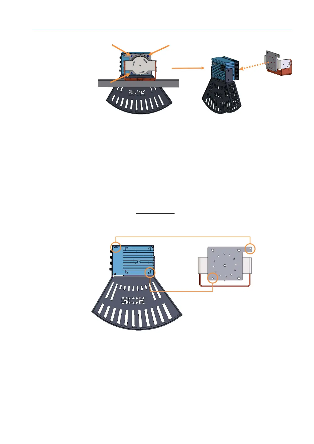
Fig. 89: Removing the 2D LiDAR sensor from the mounting plate
▸
Switch off the device.
▸
Unscrew all connecting cables from the defective device.
▸
Remove the three M6 fixing screws on the rear side of the mounting plate.
NOTE! When loosening the last screw, press the 2D LiDAR sensor against the bracket
with one hand to hold the device in place.
Remove the defective 2D LiDAR sensor from the bracket. The mounting plate remains
mounted on the frame.
▸
Mount the replacement device by following the above instructions in reverse order
(see also section 4.1 Mounting the 2D LiDAR sensor).
▸
Insert the press-fit stud of the mounting plate into the locating hole of the 2D LiDAR
sensor.
Fig. 90: Dowel pins and locating holes
▸
Press the device into place with one hand and screw the device to the mounting plate.
▸
Make sure that the device is securely screwed on.
▸
Screw the connecting cables back on.
▸
Switch the voltage supply back on.
▸
Check that the status LED lights up green after approximately 40 seconds.
Removing a
defective device
Mounting the
replacement device