Installing/Mounting
4.3 Connecting a CU240S DP or CU240S DP-F via PROFIBUS DP
Control Units CU240S
4-14 Operating Instructions, 11/2006, A5E00766042B AA
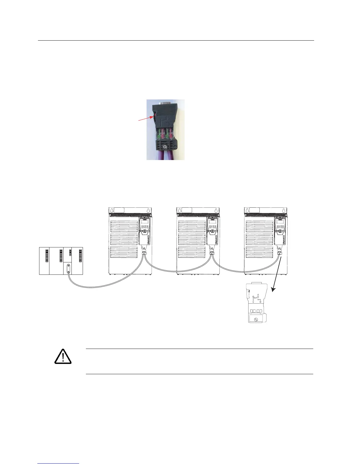
Bus terminator
Each bus segment must have a resistor network, i.e. a bus terminator, at both ends.
Where the recommended bus connectors have been used, the bus terminator can be
switched in and out by means of switches as shown in the figure below.
%XV
WHUPLQDWRU
VZLWFK
8S %XVWHUPLQDWLRQ21
'RZQ %XVWHUPLQDWLRQ2))
Figure 4-8 PROFIBUS DP bus termination switch
Using the recommended bus connectors the first and last node on the PROFIBUS network
must be terminated (as shown in the figure below), this switching of the bus terminator
provides both the 220 Ω termination and the 390 Ω biasing. The 390 Ω biasing maintains the
potential difference between the signals in the PROFIBUS network cables.
A1 B1 A2 B2
R
on
off
R
on
off
A1 B1 A2 B2
R
on
off
A1 B1 A2 B2
R
on
off
on
3/&FRQQHFWRUWHUPLQDWHG
)LQDOQRGHWHUPLQDWHG
Figure 4-9 PROFIBUS network with bus termination
Warning
It must be ensured that any node, where the biasing components of the bus are connected,
is powered at all times in which the bus is in operation.
 Loading...


