506/617
Building Technologies Division User Manual LMS14… CC1U7471en
6 The settings in detail 28.01.2015
Relay output QX22 module 2
Only QX22 of extension module 2 is switched on.
Relay output QX23 module 2
Only QX23 of extension module 2 is switched on.
Relay output QX21 module 3
Only QX21 of extension module 3 is switched on.
Relay output QX22 module 3
Only QX22 of extension module 3 is switched on.
Relay output QX23 module 3
Only QX23 of extension module 3 is switched on.
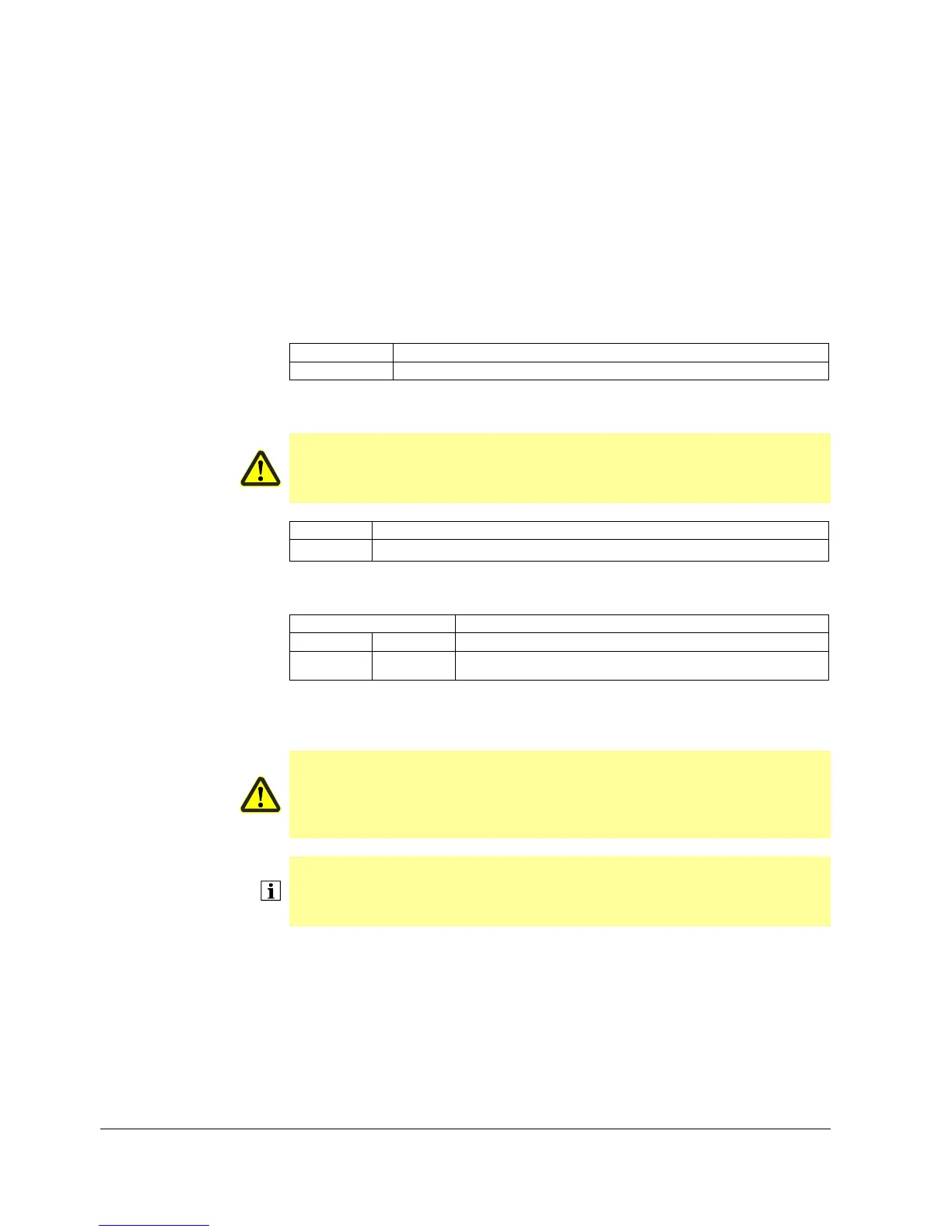
Line no. Operating line
7713 Output test P1
Here, a PWM signal for test purposes can be predefined, to be delivered via output P1.
Caution!
The PWM signal can also be preset when the burner is in operation.
When using small values for the PWM signal, it should be noted that these can lead
to fast boiler temperature increases and overheating due to low flow rates.
Line no. Operating line
7714 PWM signal P1
Display of the current PWM output via output P1.
Line no. Operating line
UX2 UX3
7716 7724
Output test UXx
A PWM signal or voltage signal (depending on Signal output UX (6072)) can be
specified here so that it can be output at the UX2 output/UX3 output for test purposes.
Caution!
The signal can still be specified even if the burner is on. Please note that if low
values are set for the PWM signal/voltage signal, a rapid temperature rise may
occur due to the minimal flow inside the boiler and, in turn, this could cause
the boiler to overheat.
Note!
Depending on what type of operating unit is used, the following operating lines either
appear on a double display that shows the signal value and type, or they appear as
two separate operating lines for the voltage and PWM.
Output test P1
PWM signal P1
Output test UXx

 Loading...