106/267
Building Technologies Basic documentation LMV37.4... CC1P7546en
10 Electronic ratio control 17.12.2018
10.3 Modulating operation
In modulating mode, it is possible to operate 2 actuators and 1 VSD. The burner‘s
output can be regulated between 20% (low-fire) and 100% (high-fire) in increments of
0.1%. Since the actuators are never allowed to operate simultaneously, the output is
increased in small steps of 1%. With a ramp-up time of 32 seconds in operating position
(from 20% to 100%), this results in a step within 400 ms.
Within such an output step, the air actuator or the VSD is operated in the first 200 ms,
and the fuel actuator in the second 200 ms.
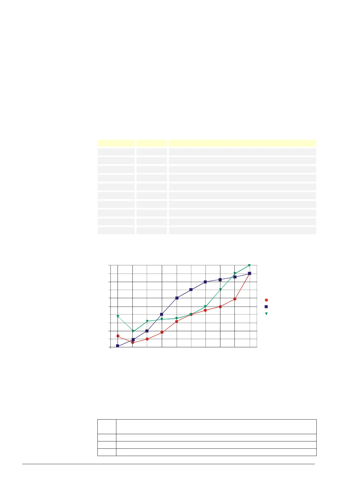
10.3.1 Definition of curves
The air-fuel ratio curves are defined by 10 curvepoints that are fixed and distributed
across the output range.
The following assignment applies:
Curvepoint Output Meaning
P0 10% Point of ignition, not approached in the operating position
P1 20% Low-fire
P2 30%
P3 40%
P4 50%
P5 60%
P6 70%
P7 80%
P8 90%
P9 100% High-fire
The actuator positions can be set with a resolution of 0.1°.
Between the curvepoints, the positions are interpolated in a linear manner.
Fuel
Air
VSD
100
90
80
70
60
50
40
30
20
10
0
P0 10 % Ignition point
P1 20 % Low-fire
P2 30 %
P3 40 %
P4 50 %
P5 60 %
P6 70 %
P7 80 %
P8 90 %
P9 100 % High-fire
Bild 385e/1109
Figure 74: Definition of curves
No. Parameter
401 Fuel-air ratio control curve fuel actuator (curve setting only)
402 Fuel-air ratio control curve air actuator (curve setting only)
403 Fuel-air ratio control curve VSD (curve setting only)
 Loading...


