148/267
Building Technologies Basic documentation LMV37.4... CC1P7546en
13 Load output X74 pin 3 17.12.2018
13 Load output X74 pin 3
The load output is only available as an alternative to VSD control. If the VSD is
deactivated, the output for the VSD delivers the current burner output. The analog
output is a voltage output and – using parameter 645 – can be switched between DC
0…10 V, DC 2…10 V and DC 0/2…10 V.
Parameter 645 Voltage range Remarks
0 DC 0…10 V No detection of line interruption
1 DC 2…10 V Detection of line interruption
possible
2 DC 0/2…10 V No detection of line interruption.
Recommended setting in
connection with Micromaster VSD
Note
When changing the analog output configuration from DC 0…10 V to DC 2…10 V or
DC 0/2…10 V, the voltage values with modulating, 2-stage and 3-stage operation
change (refer to chapter Modulating operation, chapter 2-stage operation and chapter
3-stage operation).
Conversion: New value = (initial value * 0.8) + 2
Example: Initially 2 V (2 * 0.8) + 2 = 3.6 V
Initially 5 V (5 * 0.8) + 2 = 6 V
No. Parameter
645
Configuration of analog output
0 = DC 0...10 V
1 = DC 2...10 V
2 = DC 0/2...10 V
13.1 Safe separation of mains voltage and extra
low-voltage
Caution!
The load output is designed for SELV or PELV (refer to chapter Electrical
connection of the LMV37.4).
For this reason, strict separation from the mains voltage side must be ensured!
This necessitates power supply by an external power pack (X74 pin 1, X74 pin 2).
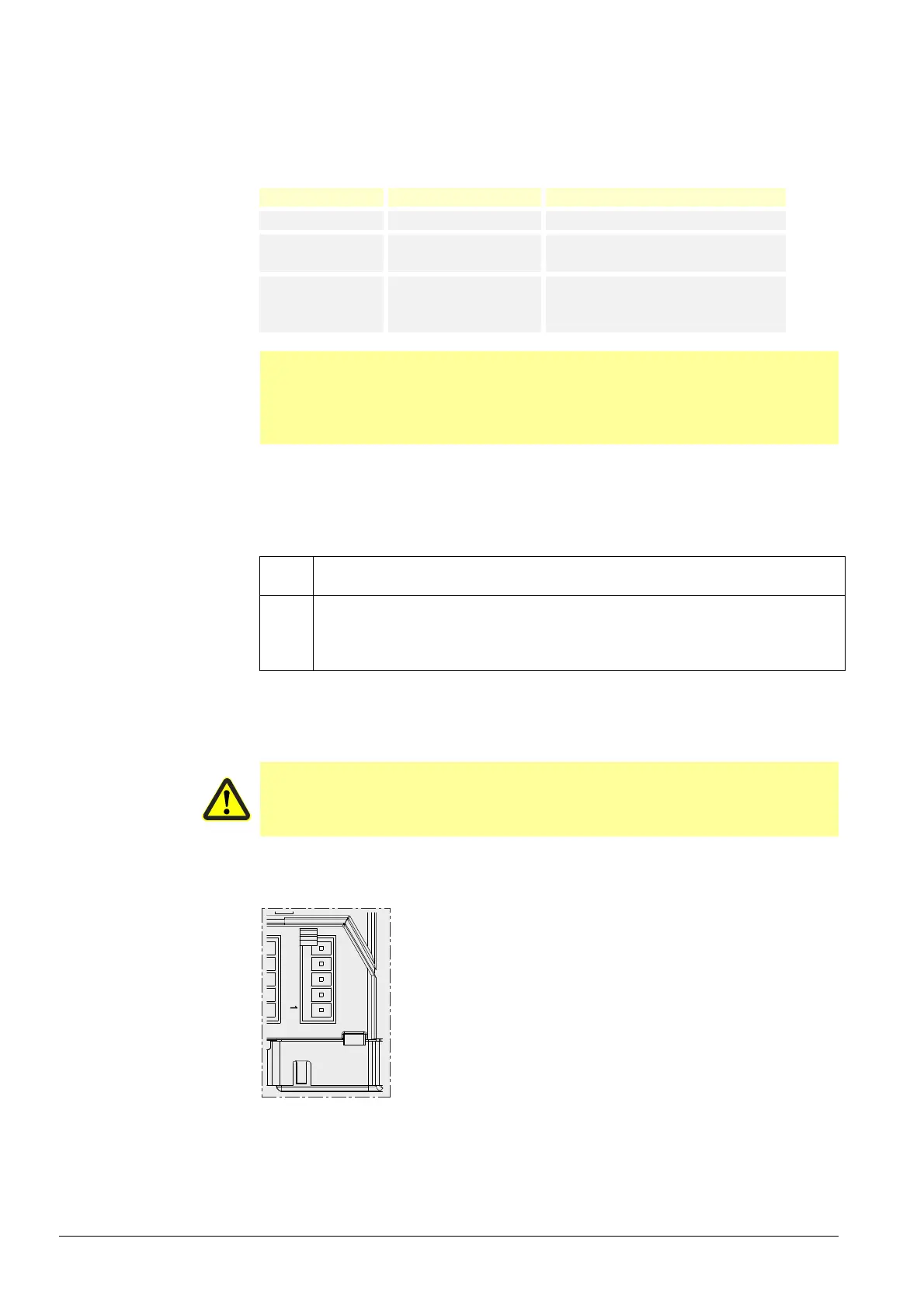
LMV...
Bild 433en/0916
VSD X74
5
4
3
Power output
2
GND
1
24 V external
Figure 92: Power output

 Loading...

