88/267
Building Technologies Basic documentation LMV37.4... CC1P7546en
7 Basic unit LMV37.4 17.12.2018
7.7.8 Legend to the sequence diagrams
Note
Not all phases, times, indices, abbreviations and symbols appear in the
individual sequence diagrams or are needed there!
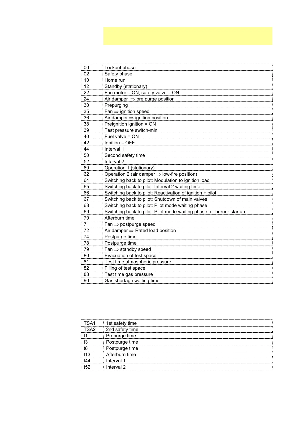
Phase numbers
00 Lockout phase
02 Safety phase
10 Home run
12 Standby (stationary)
22 Fan motor = ON, safety valve = ON
24 Air damper pre purge position
30 Prepurging
35 Fan ignition speed
36 Air damper ignition position
38 Preignition ignition = ON
39 Test pressure switch-min
40 Fuel valve = ON
42 Ignition = OFF
44 Interval 1
50 Second safety time
52 Interval 2
60 Operation 1 (stationary)
62 Operation 2 (air damper low-fire position)
64 Switching back to pilot: Modulation to ignition load
65 Switching back to pilot: Interval 2 waiting time
66 Switching back to pilot: Reactivation of ignition + pilot
67 Switching back to pilot: Shutdown of main valves
68 Switching back to pilot: Pilot mode waiting phase
69 Switching back to pilot: Pilot mode waiting phase for burner startup
70 Afterburn time
71 Fan postpurge speed
72 Air damper Rated load position
74 Postpurge time
78 Postpurge time
79 Fan standby speed
80 Evacuation of test space
81 Test time atmospheric pressure
82 Filling of test space
83 Test time gas pressure
90 Gas shortage waiting time
Valve proving is performed depending on the parameter settings:
Simultaneously with the prepurge time and/or the afterburn time.
Times
TSA1 1st safety time
TSA2 2nd safety time
t1 Prepurge time
t3 Postpurge time
t8 Postpurge time
t13 Afterburn time
t44 Interval 1
t52 Interval 2
 Loading...


