108/267
Building Technologies Basic documentation LMV37.4... CC1P7546en
10 Electronic ratio control 17.12.2018
VSD / PWM fan
For the VSD or the PWM fan, it is also possible to change the maximum speed
differential between 2 curvepoints via the no-load time for the speed measurement in
modulating operation. This is 200 ms (value 8) in the default setting and can be reduced
to 100 ms (value 4). Shortening the no-load time can result in problems in connection
with the internal speed control of the LMV37.4 and is only recommended with the control
deactivated.
The achievable maximum speed difference can be calculated based on the following
formula:
Maximum speed
100% * modulating operating ramp * (16
– no-load time speed
measurement)
differential -------------------------------------------------------------------------------------------------
(Ramp time * 128)
Between the ignition time (P0) and the low-fire point (P1), a speed differential of up to
40% can be set for the VSD or the PWM fan, independent of the selected ramp. This
means that the period of time from ignition to low-fire can vary between 4…32 seconds
(5...40 seconds ramp).
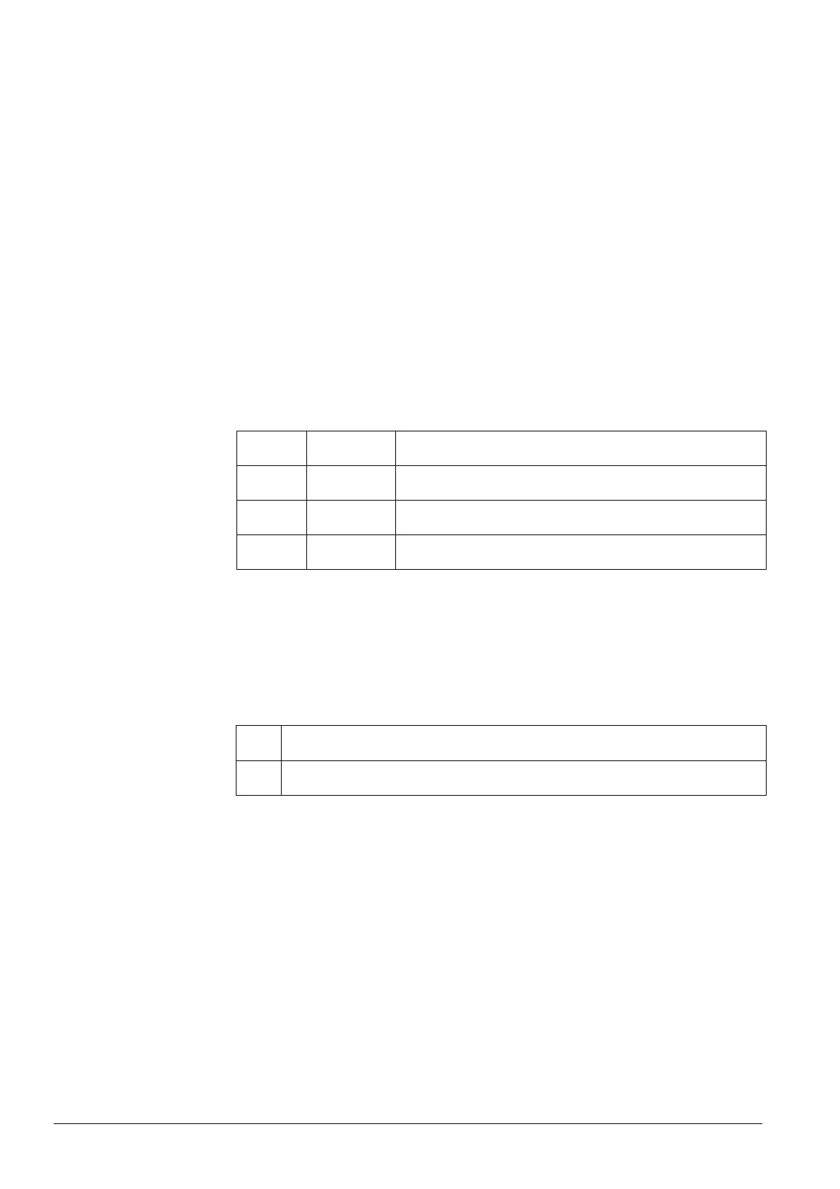
Error
code
Diagnostic
code
Meaning for the LMV37.4
84 Bit 0
Valency 1
VSD: Curve too steep in terms of ramp rate
Bit 1
Valency 2..3
Fuel actuator: Curve too steep in terms of ramp speed
Bit 2
Valency 4..7
Air actuator: Curve too steep in terms of ramp speed
The parameterized curve is steeper than is permitted at the selected actuator speed.
10.3.3 Entering the running position
The burner is ignited when ignition position P0 is reached. When entering operating
phase 60, the actuators follow the defined curves until the low-fire position is reached
(20% or parameter 545).
No. Parameter
545
Lower output limit
undefined = 20 %
10.3.4 Operating position
As demanded by the load controller, the actuators are driven along the defined 20% and
100% curves. Point of ignition P0 can only be reached via the curve settings.
 Loading...


